13.2. The Device Driver Model
Earlier versions of the Linux kernel offered few basic functionalities to the device driver developers: allocating dynamic memory, reserving a range of I/O addresses or an IRQ line, activating an interrupt service routine in response to a device's interrupt. Older hardware devices, in fact, were cumbersome and difficult to program, and two different hardware devices had little in common even if they were hosted on the same bus. Thus, there was no point in trying to offer a unifying model to the device driver developers.
Things are different now. Bus types such as PCI put strong demands on the internal design of the hardware devices; as a consequence, recent hardware devices, even of different classes, sport similar functionalities. Drivers for such devices should typically take care of:
Power management (handling of different voltage levels on the device's power line) Plug and play (transparent allocation of resources when configuring the device) Hot-plugging (support for insertion and removal of the device while the system is running)
Power management is performed globally by the kernel on every hardware device in the system. For instance, when a battery-powered computer enters the "standby" state, the kernel must force every hardware device (hard disks, graphics card, sound card, network card, bus controllers, and so on) in a low-power state. Thus, each driver of a device that can be put in the "standby" state must include a callback function that puts the hardware device in the low-power state. Moreover, the hardware devices must be put in the "standby" state in a precise order, otherwise some devices could be left in the wrong power state. For instance, the kernel must put in "standby" first the hard disks and then their disk controller, because in the opposite case it would be impossible to send commands to the hard disks.
To implement these kinds of operations, Linux 2.6 provides some data structures and helper functions that offer a unifying view of all buses, devices, and device drivers in the system; this framework is called the device driver model
.
13.2.1. The sysfs Filesystem
The sysfs
filesystem is a special filesystem similar to /proc
that is usually mounted on the /sys directory. The /proc filesystem was the first special filesystem designed to allow User Mode applications to access kernel internal data structures. The /sysfs filesystem has essentially the same objective, but it provides additional information on kernel data structures; furthermore, /sysfs is organized in a more structured way than /proc. Likely, both /proc and /sysfs will continue to coexist in the near future.
A goal of the sysfs filesystem is to expose the hierarchical relationships among the components of the device driver model. The related top-level directories of this filesystem are:
block The block devices, independently from the bus to which they are connected.
devices All hardware devices recognized by the kernel, organized according to the bus in which they are connected.
bus The buses in the system, which host the devices.
drivers The device drivers registered in the kernel.
class The types of devices in the system (audio cards, network cards, graphics cards, and so on); the same class may include devices hosted by different buses and driven by different drivers.
power Files to handle the power states of some hardware devices.
firmware Files to handle the firmware of some hardware devices.
Relationships between components of the device driver models are expressed in the sysfs filesystem as symbolic links between directories and files. For example, the /sys/block/sda/device file can be a symbolic link to a subdirectory nested in /sys/devices/pci0000:00 representing the SCSI controller connected to the PCI bus. Moreover, the /sys/block/sda/device/block file is a symbolic link to /sys/block/sda, stating that this PCI device is the controller of the SCSI disk.
The main role of regular files in the sysfs filesystem is to represent attributes of drivers and devices. For instance, the dev file in the /sys/block/hda directory contains the major and minor numbers of the master disk in the first IDE chain.
13.2.2. Kobjects
The core data structure of the device driver model is a generic data structure named kobject, which is inherently tied to the sysfs filesystem: each kobject corresponds to a directory in that filesystem.
Kobjects are embedded inside larger objectsthe so-called "containers"that describe the components of the device driver model. The descriptors of buses, devices, and drivers are typical examples of containers; for instance, the descriptor of the first partition in the first IDE disk corresponds to the /sys/block/hda/hda1 directory.
Embedding a kobject inside a container allows the kernel to:
Keep a reference counter for the container Maintain hierarchical lists or sets of containers (for instance, a sysfs directory associated with a block device includes a different subdirectory for each disk partition) Provide a User Mode view for the attributes of the container
13.2.2.1. Kobjects, ksets, and subsystems
A kobject is represented by a kobject data structure, whose fields are listed in Table 13-2.
Table 13-2. The fields of the kobject data structureType | Field | Description |
|---|
char * | k_name | Pointer to a string holding the name of the container | char [] | name | String holding the name of the container, if it fits in 20 bytes | struct k_ref | kref | The reference counter for the container | struct list_head | entry | Pointers for the list in which the kobject is inserted | struct kobject * | parent | Pointer to the parent kobject, if any | struct kset * | kset | Pointer to the containing kset | struct kobj_type * | ktype | Pointer to the kobject type descriptor | struct dentry * | dentry | Pointer to the dentry of the sysfs file associated with the kobject |
The ktype field points to a kobj_type object representing the "type" of the kobjectessentially, the type of the container that includes the kobject. The kobj_type data structure includes three fields: a release method (executed when the kobject is being freed), a sysfs_ops pointer to a table of sysfs operations, and a list of default attributes for the sysfs filesystem.
The kref field is a structure of type k_ref consisting of a single refcount field. As the name implies, this field is the reference counter for the kobject, but it may act also as the reference counter for the container of the kobject. The kobject_get( ) and kobject_put( ) functions increase and decrease, respectively, the reference counter; if the counter reaches the value zero, the resources used by the kobject are released and the release method of the kobj_type object of the kobject is executed. This method, which is usually defined only if the container of the kobject was allocated dynamically, frees the container itself.
The kobjects can be organized in a hierarchical tree by means of ksets
. A kset is a collection of kobjects of the same typethat is, included in the same type of container. The fields of the kset data structure are listed in Table 13-3.
Table 13-3. The fields of the kset data structureType | Field | Description |
|---|
struct subsystem * | subsys | Pointer to the subsystem descriptor | struct kobj_type * | ktype | Pointer to the kobject type descriptor of the kset | struct list_head | list | Head of the list of kobjects included in the kset | struct kobject | kobj | Embedded kobject (see text) | struct kset_hotplug_ops * | hotplug_ops | Pointer to a table of callback functions for kobject filtering and hot-plugging |
The list field is the head of the doubly linked circular list of kobjects included in the kset; the ktype field points to the same kobj_type descriptor shared by all kobjects in the kset.
The kobj field is a kobject embedded in the kset data structure; the parent field of the kobjects contained in the kset points to this embedded kobject. Thus, a kset is a collection of kobjects, but it relies on a kobject of higher level for reference counting and linking in the hierarchical tree. This design choice is code-efficient and allows the greatest flexibility. For instance, the kset_get( ) and kset_put( ) functions, which increase and decrease respectively the reference counter of the kset, simply invoke kobject_get( ) and kobject_put( ) on the embedded kobject; because the reference counter of a kset is merely the reference counter of the kobj kobject embedded in the kset. Moreover, thanks to the embedded kobject, the kset data structure can be embedded in a "container" object, exactly as for the kobject data structure. Finally, a kset can be made a member of another kset: it suffices to insert the embedded kobject in the higher-level kset.
Collections of ksets called subsystems
also exist. A subsystem may include ksets of different types, and it is represented by a subsystem data structure having just two fields:
kset An embedded kset that stores the ksets included in the subsystem
rwsem A read-write semaphore that protects all ksets and kobjects recursively included in the subsystem
Even the subsystem data structure can be embedded in a larger "container" object; the reference counter of the container is thus the reference counter of the embedded subsystemthat is, the reference counter of the kobject embedded in the kset embedded in the subsystem. The subsys_get( ) and subsys_put( ) functions respectively increase and decrease this reference counter.
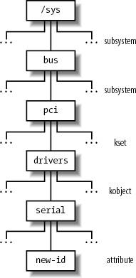
Figure 13-3 illustrates an example of the device driver model hierarchy. The bus subsystem includes a pci subsystem, which, in turn, includes a drivers kset. This kset contains a serial kobjectcorresponding to the device driver for the serial porthaving a single new-id attribute.
13.2.2.2. Registering kobjects, ksets, and subsystems
As a general rule, if you want a kobject, kset, or subsystem to appear in the sysfs subtree, you must first register it. The directory associated with a kobject always appears in the directory of the parent kobject. For instance, the directories of kobjects included in the same kset appear in the directory of the kset itself. Therefore, the structure of the sysfs subtree represents the hierarchical relationships between the various registered kobjects and, consequently, between the various container objects. Usually, the top-level directories of the sysfs filesystem are associated with the registered subsystems.
The kobject_register( ) function initializes a kobject and adds the corresponding directory to the sysfs filesystem. Before invoking it, the caller should set the kset field in the kobject so that it points to the parent kset, if any. The kobject_unregister( ) function removes a kobject's directory from the sysfs filesystem. To make life easier for kernel developers, Linux also offers the kset_register( ) and kset_unregister( ) functions, and the subsystem_register( ) and subsystem_unregister( ) functions, but they are essentially wrapper functions around kobject_register( ) and kobject_unregister( ).
As stated before, many kobject directories include regular files called attributes
. The sysfs_create_file( ) function receives as its parameters the addresses of a kobject and an attribute descriptor, and creates the special file in the proper directory. Other relationships between the objects represented in the sysfs filesystem are established by means of symbolic links: the sysfs_create_link() function creates a symbolic link for a given kobject in a directory associated with another kobject.
13.2.3. Components of the Device Driver Model
The device driver model is built upon a handful of basic data structures, which represent buses, devices, device drivers, etc. Let us examine them.
13.2.3.1. Devices
Each device in the device driver model is represented by a device object, whose fields are shown in Table 13-4.
Table 13-4. The fields of the device objectType | Field | Description |
|---|
struct list_head | node | Pointers for the list of sibling devices | struct list_head | bus_list | Pointers for the list of devices on the same bus type | struct list_head | driver_list | Pointers for the driver's list of devices | struct list_head | children | Head of the list of children devices | struct device * | parent | Pointer to the parent device | struct kobject | kobj | Embedded kobject | char [] | bus_id | Device position on the hosting bus | struct bus_type * | bus | Pointer to the hosting bus | struct device_driver * | driver | Pointer to the controlling device driver | void * | driver_data | Pointer to private data for the driver | void * | platform_data | Pointer to private data for legacy device drivers | struct dev_pm_info | power | Power management information | unsigned long | detach_state | Power state to be entered when unloading the device driver | unsigned long long * | dma_mask | Pointer to the DMA mask of the device (see the later section "Direct Memory Access (DMA)") | unsigned long long | coherent_dma_mask | Mask for coherent DMA of the device | struct list_head | dma_pools | Head of a list of aggregate DMA buffers | struct dma_coherent_mem * | dma_mem | Pointer to a descriptor of the coherent DMA memory used by the device (see the later section "Direct Memory Access (DMA)") | void (*)(struct device *) | release | Callback function for releasing the device descriptor |
The device objects are globally collected in the devices_subsys subsystem, which is associated with the /sys/devices directory (see the earlier section "Kobjects"). The devices are organized hierarchically: a device is the "parent" of some "children" devices if the children devices cannot work properly without the parent device. For instance, in a PCI-based computer, a bridge between the PCI bus and the USB bus is the parent device of every device hosted on the USB bus. The parent field of the device object points to the descriptor of the parent device, the children field is the head of the list of children devices, and the node field stores the pointers to the adjacent elements in the children list. The parenthood relationships between the kobjects embedded in the device objects reflect also the device hierarchy; thus, the structure of the directories below /sys/devices matches the physical organization of the hardware devices.
Each driver keeps a list of device objects including all managed devices; the driver_list field of the device object stores the pointers to the adjacent elements, while the driver field points to the descriptor of the device driver. For each bus type, moreover, there is a list including all devices that are hosted on the buses of the given type; the bus_list field of the device object stores the pointers to the adjacent elements, while the bus field points to the bus type descriptor.
A reference counter keeps track of the usage of the device object; it is included in the kobj kobject embedded in the descriptor. The counter is increased by invoking get_device( ), and it is decreased by invoking put_device( ).
The device_register( ) function inserts a new device object in the device driver model, and automatically creates a new directory for it under /sys/devices
. Conversely, the device_unregister( ) function removes a device from the device driver model.
Usually, the device object is statically embedded in a larger descriptor. For instance, PCI devices are described by pci_dev data structures; the dev field of this structure is a device object, while the other fields are specific to the PCI bus. The device_register( ) and device_unregister( ) functions are executed when the device is being registered or de-registered in the PCI kernel layer.
13.2.3.2. Drivers
Each driver in the device driver model is described by a device_driver object, whose fields are listed in Table 13-5.
Table 13-5. The fields of the device_driver objectType | Field | Description |
|---|
char * | name | Name of the device driver | struct bus_type * | bus | Pointer to descriptor of the bus that hosts the supported devices | struct semaphore | unload_sem | Semaphore to forbid device driver unloading; it is released when the reference counter reaches zero | struct kobject | kobj | Embedded kobject | struct list_head | devices | Head of the list including all devices supported by the driver | struct module * | owner | Identifies the module that implements the device driver, if any (see Appendix B) | int (*)(struct device *) | probe | Method for probing a device (checking that it can be handled by the device driver) | int (*)(struct device *) | remove | Method invoked on a device when it is removed | void (*)(struct device *) | shutdown | Method invoked on a device when it is powered off (shut down) | int (*)(struct device *, unsigned long, unsigned long) | suspend | Method invoked on a device when it is put in low-power state | int (*)(struct device *, unsigned long) | resume | Method invoked on a device when it is put back in the normal state (full power) |
The device_driver object includes four methods for handling hot-plugging, plug and play, and power management. The probe method is invoked whenever a bus device driver discovers a device that could possibly be handled by the driver; the corresponding function should probe the hardware to perform further checks on the device. The remove method is invoked on a hot-pluggable device whenever it is removed; it is also invoked on every device handled by the driver when the driver itself is unloaded. The shutdown, suspend, and resume methods are invoked on a device when the kernel must change its power state.
The reference counter included in the kobj kobject embedded in the descriptor keeps track of the usage of the device_driver object. The counter is increased by invoking get_driver( ), and it is decreased by invoking put_driver( ).
The driver_register( ) function inserts a new device_driver object in the device driver model, and automatically creates a new directory for it in the sysfs filesystem. Conversely, the driver_unregister( ) function removes a driver from the device driver model.
Usually, the device_driver object is statically embedded in a larger descriptor. For instance, PCI device drivers
are described by pci_driver data structures; the driver field of this structure is a device_driver object, while the other fields are specific to the PCI bus.
13.2.3.3. Buses
Each bus type supported by the kernel is described by a bus_type object, whose fields are listed in Table 13-6.
Table 13-6. The fields of the bus_type objectType | Field | Description |
|---|
char * | name | Name of the bus type | struct subsystem | subsys | Kobject subsystem associated with this bus type | struct kset | drivers | The set of kobjects of the drivers | struct kset | devices | The set of kobjects of the devices | struct bus_attribute * | bus_attrs | Pointer to the object including the bus attributes and the methods for exporting them to the sysfs filesystem | struct device_attribute * | dev_attrs | Pointer to the object including the device attributes and the methods for exporting them to the sysfs filesystem | struct driver_attribute * | drv_attrs | Pointer to the object including the device driver attributes and the methods for exporting them to the sysfs filesystem | int (*)(struct device *, struct device_driver *) | match | Method for checking whether a given driver supports a given device | int (*)(struct device *, char **, int, char *, int) | hotplug | Method invoked when a device is being registered | int (*)(struct device *, unsigned long) | suspend | Method for saving the hardware context state and changing the power level of a device | int (*)(struct device *) | resume | Method for changing the power level and restoring the hardware context of a device |
Each bus_type object includes an embedded subsystem; the subsystem stored in the bus_subsys variable collects all subsystems embedded in the bus_type objects. The bus_subsys subsystem is associated with the /sys/bus directory; thus, for example, there exists a /sys/bus/pci directory associated with the PCI bus type. The per-bus subsystem typically includes only two ksets named drivers and devices (corresponding to the drivers and devices fields of the bus_type object, respectively).
The drivers kset contains the device_driver descriptors of all device drivers pertaining to the bus type, while the devices kset contains the device descriptors of all devices of the given bus type. Because the directories of the devices' kobjects already appear in the sysfs filesystem under /sys/devices, the devices directory of the per-bus subsystem stores symbolic links pointing to directories under /sys/devices. The bus_for_each_drv( ) and bus_for_each_dev( ) functions iterate over the elements of the lists of drivers and devices, respectively.
The match method is executed when the kernel must check whether a given device can be handled by a given driver. Even if each device's identifier has a format specific to the bus that hosts the device, the function that implements the method is usually simple, because it searches the device's identifier in the driver's table of supported identifiers. The hotplug method is executed when a device is being registered in the device driver model; the implementing function should add bus-specific information to be passed as environment variables to a User Mode program that is notified about the new available device (see the later section "Device Driver Registration"). Finally, the suspend and resume methods are executed when a device on a bus of the given type must change its power state.
13.2.3.4. Classes
Each class is described by a class object. All class objects belong to the class_subsys subsystem associated with the /sys/class directory. Each class object, moreover, includes an embedded subsystem; thus, for example, there exists a /sys/class/input directory associated with the input class of the device driver model.
Each class object includes a list of class_device descriptors, each of which represents a single logical device belonging to the class. The class_device structure includes a dev field that points to a device descriptor, thus a logical device always refers to a given device in the device driver model. However, there can be several class_device descriptors that refer to the same device. In fact, a hardware device might include several different sub-devices, each of which requires a different User Mode interface. For example, the sound card is a hardware device that usually includes a DSP, a mixer, a game port interface, and so on; each sub-device requires its own User Mode interface, thus it is associated with its own directory in the sysfs filesystem.
Device drivers in the same class are expected to offer the same functionalities to the User Mode applications; for instance, all device drivers of sound cards should offer a way to write sound samples to the DSP.
The classes
of the device driver model are essentially aimed to provide a standard method for exporting to User Mode applications the interfaces of the logical devices
. Each class_device descriptor embeds a kobject having an attribute (special file) named dev. Such attribute stores the major and minor numbers of the device file that is needed to access to the corresponding logical device (see the next section).
13.3. Device Files
As mentioned in Chapter 1, Unix-like operating systems are based on the notion of a file, which is just an information container structured as a sequence of bytes. According to this approach, I/O devices are treated as special files called device files
; thus, the same system calls used to interact with regular files on disk can be used to directly interact with I/O devices. For example, the same write( )
system call may be used to write data into a regular file or to send it to a printer by writing to the /dev/lp0 device file.
According to the characteristics of the underlying device drivers, device files can be of two types: block or character. The difference between the two classes of hardware devices is not so clear-cut. At least we can assume the following:
The data of a block device can be addressed randomly, and the time needed to transfer a data block is small and roughly the same, at least from the point of view of the human user. Typical examples of block devices
are hard disks, floppy disks
, CD-ROM drives, and DVD players. The data of a character device either cannot be addressed randomly (consider, for instance, a sound card), or they can be addressed randomly, but the time required to access a random datum largely depends on its position inside the device (consider, for instance, a magnetic tape driver).
Network cards are a notable exception to this schema, because they are hardware devices that are not directly associated with device files.
Device files have been in use since the early versions of the Unix operating system. A device file is usually a real file stored in a filesystem. Its inode, however, doesn't need to include pointers to blocks of data on the disk (the file's data) because there are none. Instead, the inode must include an identifier of the hardware device corresponding to the character or block device file.
Traditionally, this identifier consists of the type of device file (character or block) and a pair of numbers. The first number, called the major number, identifies the device type. Traditionally, all device files that have the same major number and the same type share the same set of file operations, because they are handled by the same device driver. The second number, called the minor number, identifies a specific device among a group of devices that share the same major number. For instance, a group of disks managed by the same disk controller have the same major number and different minor numbers
.
The mknod( )
system call is used to create device files. It receives the name of the device file, its type, and the major and minor numbers as its parameters. Device files are usually included in the /dev directory. Table 13-7 illustrates the attributes of some device files. Notice that character and block devices have independent numbering, so block device (3,0) is different from character device (3,0).
Table 13-7. Examples of device filesName | Type | Major | Minor | Description |
|---|
/dev/fd0 | block | 2 | 0 | Floppy disk | /dev/hda | block | 3 | 0 | First IDE disk | /dev/hda2 | block | 3 | 2 | Second primary partition of first IDE disk | /dev/hdb | block | 3 | 64 | Second IDE disk | /dev/hdb3 | block | 3 | 67 | Third primary partition of second IDE disk | /dev/ttyp0 | char | 3 | 0 | Terminal | /dev/console | char | 5 | 1 | Console | /dev/lp1 | char | 6 | 1 | Parallel printer | /dev/ttyS0 | char | 4 | 64 | First serial port | /dev/rtc | char | 10 | 135 | Real-time clock | /dev/null | char | 1 | 3 | Null device (black hole) |
Usually, a device file is associated with a hardware device (such as a hard diskfor instance, /dev/hda) or with some physical or logical portion of a hardware device (such as a disk partitionfor instance, /dev/hda2). In some cases, however, a device file is not associated with any real hardware device, but represents a fictitious logical device. For instance, /dev/null is a device file corresponding to a "black hole;" all data written into it is simply discarded, and the file always appears empty.
As far as the kernel is concerned, the name of the device file is irrelevant. If you create a device file named /tmp/disk of type "block" with the major number 3 and minor number 0, it would be equivalent to the /dev/hda device file shown in the table. On the other hand, device filenames may be significant for some application programs. For example, a communication program might assume that the first serial port is associated with the /dev/ttyS0 device file. But most application programs can be configured to interact with arbitrarily named device files.
13.3.1. User Mode Handling of Device Files
In traditional Unix systems (and in earlier versions of Linux), the major and minor numbers of the device files are 8 bits long. Thus, there could be at most 65,536 block device files and 65,536 character device files. You might expect they will suffice, but unfortunately they don't.
The real problem is that device files are traditionally allocated once and forever in the /dev directory; therefore, each logical device in the system should have an associated device file with a well-defined device number. The official registry of allocated device numbers and /dev directory nodes is stored in the Documentation/devices.txt file; the macros corresponding to the major numbers of the devices may also be found in the include/linux/major.h file.
Unfortunately, the number of different hardware devices is so large nowadays that almost all device numbers have already been allocated. The official registry of device numbers works well for the average Linux system; however, it may not be well suited for large-scale systems. Furthermore, high-end systems may use hundreds or thousands of disks of the same type, and an 8-bit minor number is not sufficient. For instance, the registry reserves device numbers for 16 SCSI disks having 15 partitions each; if a high-end system has more than 16 SCSI disks, the standard assignment of major and minor numbers has to be changeda non trivial task that requires modifying the kernel source code and makes the system hard to maintain.
In order to solve this kind of problem, the size of the device numbers has been increased in Linux 2.6: the major number is now encoded in 12 bits, while the minor number is encoded in 20 bits. Both numbers are usually kept in a single 32-bit variable of type dev_t; the MAJOR and MINOR macros extract the major and minor numbers, respectively, from a dev_t value, while the MKDEV macro encodes the two device numbers in a dev_t value. For backward compatibility, the kernel handles properly old device files encoded with 16-bit device numbers.
The additional available device numbers are not being statically allocated in the official registry, because they should be used only when dealing with unusual demands for device numbers. Actually, today's preferred way to deal with device files is highly dynamic, both in the device number assignment and in the device file creation.
13.3.1.1. Dynamic device number assignment
Each device driver specifies in the registration phase the range of device numbers that it is going to handle (see the later section "Device Driver Registration"). The driver can, however, require the allocation of an interval of device numbers without specifying the exact values: in this case, the kernel allocates a suitable range of numbers and assigns them to the driver.
Therefore, device drivers of new hardware devices no longer require an assignment in the official registry of device numbers; they can simply use whatever numbers are currently available in the system.
In this case, however, the device file cannot be created once and forever; it must be created right after the device driver initialization with the proper major and minor numbers. Thus, there must be a standard way to export the device numbers used by each driver to the User Mode applications. As we have seen in the earlier section "Components of the Device Driver Model," the device driver model provides an elegant solution: the major and minor numbers are stored in the dev attributes contained in the subdirectories of /sys/class.
13.3.1.2. Dynamic device file creation
The Linux kernel can create the device files dynamically: there is no need to fill the /dev directory with the device files of every conceivable hardware device, because the device files can be created "on demand." Thanks to the device driver model, the kernel 2.6 offers a very simple way to do so. A set of User Mode programs, collectively known as the udev toolset, must be installed in the system. At the system startup the /dev directory is emptied, then a udev program scans the subdirectories of /sys/class looking for the dev files. For each such file, which represents a combination of major and minor number for a logical device supported by the kernel, the program creates a corresponding device file in /dev. It also assigns device filenames and creates symbolic links according to a configuration file, in such a way to resemble the traditional naming scheme for Unix device files. Eventually, /dev is filled with the device files of all devices supported by the kernel on this system, and nothing else.
Often a device file is created after the system has been initialized. This happens either when a module containing a device driver for a still unsupported device is loaded, or when a hot-pluggable devicesuch as a USB peripheralis plugged in the system. The udev toolset can automatically create the corresponding device file, because the device driver model supports device hotplugging
. Whenever a new device is discovered, the kernel spawns a new process that executes the User Mode /sbin/hotplug shell script, passing to it any useful information on the discovered device as environment variables. The User Mode scripts usually reads a configuration file and takes care of any operation required to complete the initialization of the new device. If udev is installed, the script also creates the proper device file in the /dev directory.
13.3.2. VFS Handling of Device Files
Device files live in the system directory tree but are intrinsically different from regular files and directories. When a process accesses a regular file, it is accessing some data blocks in a disk partition through a filesystem; when a process accesses a device file, it is just driving a hardware device. For instance, a process might access a device file to read the room temperature from a digital thermometer connected to the computer. It is the VFS's responsibility to hide the differences between device files and regular files from application programs.
To do this, the VFS changes the default file operations of a device file when it is opened; as a result, each system call on the device file is translated to an invocation of a device-related function instead of the corresponding function of the hosting filesystem. The device-related function acts on the hardware device to perform the operation requested by the process.
Let's suppose that a process executes an open( )
system call on a device file (either of type block or character). The operations performed by the system call have already been described in the section "The open( ) System Call" in Chapter 12. Essentially, the corresponding service routine resolves the pathname to the device file and sets up the corresponding inode object, dentry object, and file object.
The inode object is initialized by reading the corresponding inode on disk through a suitable function of the filesystem (usually ext2_read_inode( ) or ext3_read_inode( ); see Chapter 18). When this function determines that the disk inode is relative to a device file, it invokes init_special_inode( ), which initializes the i_rdev field of the inode object to the major and minor numbers of the device file, and sets the i_fop field of the inode object to the address of either the def_blk_fops or the def_chr_fops file operation table, according to the type of device file. The service routine of the open( ) system call also invokes the dentry_open( ) function, which allocates a new file object and sets its f_op field to the address stored in i_fopthat is, to the address of def_blk_fops or def_chr_fops once again. Thanks to these two tables, every system call issued on a device file will activate a device driver's function rather than a function of the underlying filesystem.
|
13.4. Device Drivers
A device driver is the set of kernel routines that makes a hardware device respond to the programming interface defined by the canonical set of VFS functions (open, read, lseek, ioctl, and so forth) that control a device. The actual implementation of all these functions is delegated to the device driver. Because each device has a different I/O controller, and thus different commands and different state information, most I/O devices have their own drivers.
There are many types of device drivers
. They mainly differ in the level of support that they offer to the User Mode applications, as well as in their buffering strategies for the data collected from the hardware devices. Because these choices greatly influence the internal structure of a device driver, we discuss them in the sections "Direct Memory Access (DMA)" and "Buffering Strategies for Character Devices."
A device driver does not consist only of the functions that implement the device file operations. Before using a device driver, several activities must have taken place. We'll examine them in the following sections.
13.4.1. Device Driver Registration
We know that each system call issued on a device file is translated by the kernel into an invocation of a suitable function of a corresponding device driver. To achieve this, a device driver must register itself. In other words, registering
a device driver means allocating a new device_driver descriptor, inserting it in the data structures of the device driver model (see the earlier section "Components of the Device Driver Model"), and linking it to the corresponding device file(s). Accesses to device files whose corresponding drivers have not been previously registered return the error code -ENODEV.
If a device driver is statically compiled in the kernel, its registration is performed during the kernel initialization phase. Conversely, if a device driver is compiled as a kernel module (see Appendix B), its registration is performed when the module is loaded. In the latter case, the device driver can also unregister itself when the module is unloaded.
Let us consider, for instance, a generic PCI device. To properly handle it, its device driver must allocate a descriptor of type pci_driver, which is used by the PCI kernel layer to handle the device. After having initialized some fields of this descriptor, the device driver invokes the pci_register_driver( ) function. Actually, the pci_driver descriptor includes an embedded device_driver descriptor (see the earlier section "Components of the Device Driver Model"); the pci_register_function( ) simply initializes the fields of the embedded driver descriptor and invokes driver_register( ) to insert the driver in the data structures of the device driver model.
When a device driver is being registered, the kernel looks for unsupported hardware devices that could be possibly handled by the driver. To do this, it relies on the match method of the relevant bus_type bus type descriptor, and on the probe method of the device_driver object. If a hardware device that can be handled by the driver is discovered, the kernel allocates a device object and invokes device_register( ) to insert the device in the device driver model.
13.4.2. Device Driver Initialization
Registering a device driver and initializing it are two different things. A device driver is registered as soon as possible, so User Mode applications can use it through the corresponding device files. In contrast, a device driver is initialized at the last possible moment. In fact, initializing a driver means allocating precious resources of the system, which are therefore not available to other drivers.
We already have seen an example in the section "I/O Interrupt Handling" in Chapter 4: the assignment of IRQs to devices is usually made dynamically, right before using them, because several devices may share the same IRQ line. Other resources that can be allocated at the last possible moment are page frames for DMA transfer buffers and the DMA channel itself (for old non-PCI devices such as the floppy disk driver).
To make sure the resources are obtained when needed but are not requested in a redundant manner when they have already been granted, device drivers usually adopt the following schema:
A usage counter keeps track of the number of processes that are currently accessing the device file. The counter is increased in the open method of the device file and decreased in the release method. The open method checks the value of the usage counter before the increment. If the counter is zero, the device driver must allocate the resources and enable interrupts and DMA on the hardware device. The release method checks the value of the usage counter after the decrement. If the counter is zero, no more processes are using the hardware device. If so, the method disables interrupts and DMA on the I/O controller, and then releases the allocated resources.
13.4.3. Monitoring I/O Operations
The duration of an I/O operation is often unpredictable. It can depend on mechanical considerations (the current position of a disk head with respect to the block to be transferred), on truly random events (when a data packet arrives on the network card), or on human factors (when a user presses a key on the keyboard or when she notices that a paper jam occurred in the printer). In any case, the device driver that started an I/O operation must rely on a monitoring
technique that signals either the termination of the I/O operation or a time-out.
In the case of a terminated operation, the device driver reads the status register of the I/O interface to determine whether the I/O operation was carried out successfully. In the case of a time-out, the driver knows that something went wrong, because the maximum time interval allowed to complete the operation elapsed and nothing happened.
The two techniques available to monitor the end of an I/O operation are called the polling mode
and the interrupt mode.
13.4.3.1. Polling mode
According to this technique, the CPU checks (polls) the device's status register repeatedly until its value signals that the I/O operation has been completed. We have already encountered a technique based on polling in the section "Spin Locks" in Chapter 5: when a processor tries to acquire a busy spin lock, it repeatedly polls the variable until its value becomes 0. However, polling applied to I/O operations is usually more elaborate, because the driver must also remember to check for possible time-outs. A simple example of polling looks like the following:
     for (;;) {
         if (read_status(device) & DEVICE_END_OPERATION) break;
         if (--count == 0) break;
     }
The count variable, which was initialized before entering the loop, is decreased at each iteration, and thus can be used to implement a rough time-out mechanism. Alternatively, a more precise time-out mechanism could be implemented by reading the value of the tick counter jiffies at each iteration (see the section "Updating the Time and Date" in Chapter 6) and comparing it with the old value read before starting the wait loop.
If the time required to complete the I/O operation is relatively high, say in the order of milliseconds, this schema becomes inefficient because the CPU wastes precious machine cycles while waiting for the I/O operation to complete. In such cases, it is preferable to voluntarily relinquish the CPU after each polling operation by inserting an invocation of the schedule( ) function inside the loop.
13.4.3.2. Interrupt mode
Interrupt mode can be used only if the I/O controller is capable of signaling, via an IRQ line, the end of an I/O operation.
We'll show how interrupt mode
works on a simple case. Let's suppose we want to implement a driver for a simple input character device. When the user issues a read( )
system call on the corresponding device file, an input command is sent to the device's control register. After an unpredictably long time interval, the device puts a single byte of data in its input register. The device driver then returns this byte as the result of the read( ) system call.
This is a typical case in which it is preferable to implement the driver using the interrupt mode. Essentially, the driver includes two functions:
The foo_read( ) function that implements the read method of the file object. The foo_interrupt( ) function that handles the interrupt.
The foo_read( ) function is triggered whenever the user reads the device file:
     ssize_t foo_read(struct file *filp, char *buf, size_t count,
                      loff_t *ppos)
     {
         foo_dev_t * foo_dev = filp->private_data;
         if (down_interruptible(&foo_dev->sem)
             return -ERESTARTSYS;
         foo_dev->intr = 0;
         outb(DEV_FOO_READ, DEV_FOO_CONTROL_PORT);
         wait_event_interruptible(foo_dev->wait, (foo_dev->intr=  =1));
         if (put_user(foo_dev->data, buf))
             return -EFAULT;
         up(&foo_dev->sem);
         return 1;
     }
The device driver relies on a custom descriptor of type foo_dev_t; it includes a semaphore sem that protects the hardware device from concurrent accesses, a wait queue wait, a flag intr that is set when the device issues an interrupt, and a single-byte buffer data that is written by the interrupt handler and read by the read method. In general, all I/O drivers that use interrupts rely on data structures accessed by both the interrupt handler and the read and write methods. The address of the foo_dev_t descriptor is usually stored in the private_data field of the device file's file object or in a global variable.
The main operations of the foo_read( ) function are the following:
Acquires the foo_dev->sem semaphore, thus ensuring that no other process is accessing the device. Issues the read command to the I/O device. Executes wait_event_interruptible to suspend the process until the intr flag becomes 1. This macro is described in the section "Wait queues" in Chapter 3.
After some time, our device issues an interrupt to signal that the I/O operation is completed and that the data is ready in the proper DEV_FOO_DATA_PORT data port. The interrupt handler sets the intr flag and wakes the process. When the scheduler decides to reexecute the process, the second part of foo_read( ) is executed and does the following:
Copies the character ready in the foo_dev->data variable into the user address space. Terminates after releasing the foo_dev->sem semaphore.
For simplicity, we didn't include any time-out control. In general, time-out control is implemented through static or dynamic timers (see Chapter 6); the timer must be set to the right time before starting the I/O operation and removed when the operation terminates.
Let's now look at the code of the foo_interrupt( ) function:
     irqreturn_t foo_interrupt(int irq, void *dev_id, struct pt_regs *regs)
     {
         foo->data = inb(DEV_FOO_DATA_PORT);
         foo->intr = 1;
         wake_up_interruptible(&foo->wait);
         return 1;
     }
The interrupt handler reads the character from the input register of the device and stores it in the data field of the foo_dev_t descriptor of the device driver pointed to by the foo global variable. It then sets the intr flag and invokes wake_up_interruptible( ) to wake the process blocked in the foo->wait wait queue.
Notice that none of the three parameters are used by our interrupt handler. This is a rather common case.
13.4.4. Accessing the I/O Shared Memory
Depending on the device and on the bus type, I/O shared memory in the PC's architecture may be mapped within different physical address ranges. Typically:
For most devices connected to the ISA bus The I/O shared memory is usually mapped into the 16-bit physical addresses ranging from 0xa0000 to 0xfffff; this gives rise to the "hole" between 640 KB and 1 MB mentioned in the section "Physical Memory Layout" in Chapter 2.
For devices connected to the PCI bus The I/O shared memory is mapped into 32-bit physical addresses near the 4 GB boundary. This kind of device is much simpler to handle.
A few years ago, Intel introduced the Accelerated Graphics Port (AGP) standard, which is an enhancement of PCI for high-performance graphic cards. Beside having its own I/O shared memory, this kind of card is capable of directly addressing portions of the motherboard's RAM by means of a special hardware circuit named Graphics Address Remapping Table (GART
). The GART circuitry enables AGP cards to sustain much higher data transfer rates than older PCI cards. From the kernel's point of view, however, it doesn't really matter where the physical memory is located, and GART-mapped memory is handled like the other kinds of I/O shared memory.
How does a device driver access an I/O shared memory location? Let's start with the PC's architecture, which is relatively simple to handle, and then extend the discussion to other architectures.
Remember that kernel programs act on linear addresses, so the I/O shared memory locations must be expressed as addresses greater than PAGE_OFFSET. In the following discussion, we assume that PAGE_OFFSET is equal to 0xc0000000that is, that the kernel linear addresses are in the fourth gigabyte.
Device drivers must translate I/O physical addresses of I/O shared memory locations into linear addresses in kernel space. In the PC architecture, this can be achieved simply by ORing the 32-bit physical address with the 0xc0000000 constant. For instance, suppose the kernel needs to store the value in the I/O location at physical address 0x000b0fe4 in t1 and the value in the I/O location at physical address 0xfc000000 in t2. One might think that the following statements could do the job:
     t1 = *((unsigned char *)(0xc00b0fe4));
     t2 = *((unsigned char *)(0xfc000000));
During the initialization phase, the kernel maps the available RAM's physical addresses into the initial portion of the fourth gigabyte of the linear address space. Therefore, the Paging Unit maps the 0xc00b0fe4 linear address appearing in the first statement back to the original I/O physical address 0x000b0fe4, which falls inside the "ISA hole" between 640 KB and 1 MB (see the section "Paging in Linux" in Chapter 2). This works fine.
There is a problem, however, for the second statement, because the I/O physical address is greater than the last physical address of the system RAM. Therefore, the 0xfc000000 linear address does not correspond to the 0xfc000000 physical address. In such cases, the kernel Page Tables must be modified to include a linear address that maps the I/O physical address. This can be done by invoking the ioremap( ) or ioremap_nocache( ) functions. The first function, which is similar to vmalloc( ), invokes get_vm_area( ) to create a new vm_struct descriptor (see the section "Descriptors of Noncontiguous Memory Areas" in Chapter 8) for a linear address interval that has the size of the required I/O shared memory area. The functions then update the corresponding Page Table entries of the canonical kernel Page Tables appropriately. The ioremap_nocache( ) function differs from ioremap( ) in that it also disables the hardware cache when referencing the remapped linear addresses properly.
The correct form for the second statement might therefore look like:
     io_mem = ioremap(0xfb000000, 0x200000);
     t2 = *((unsigned char *)(io_mem + 0x100000));
The first statement creates a new 2 MB linear address interval, which maps physical addresses starting from 0xfb000000; the second one reads the memory location that has the 0xfc000000 address. To remove the mapping later, the device driver must use the iounmap( ) function.
On some architectures other than the PC, I/O shared memory cannot be accessed by simply dereferencing the linear address pointing to the physical memory location. Therefore, Linux defines the following architecture-dependent functions, which should be used when accessing I/O shared memory:
readb( ), readw( ), readl( ) Reads 1, 2, or 4 bytes, respectively, from an I/O shared memory location
writeb( ), writew( ), writel( ) Writes 1, 2, or 4 bytes, respectively, into an I/O shared memory location
memcpy_fromio( ), memcpy_toio( ) Copies a block of data from an I/O shared memory location to dynamic memory and vice versa
memset_io( ) Fills an I/O shared memory area with a fixed value
The recommended way to access the 0xfc000000 I/O location is thus:
     io_mem = ioremap(0xfb000000, 0x200000);
     t2 = readb(io_mem + 0x100000);
Thanks to these functions, all dependencies on platform-specific ways of accessing the I/O shared memory can be hidden.
13.4.5. Direct Memory Access (DMA)
In the original PC architecture, the CPU is the only bus master of the system, that is, the only hardware device that drives the address/data bus in order to fetch and store values in the RAM's locations. With more modern bus architectures such as PCI, each peripheral can act as bus master, if provided with the proper circuitry. Thus, nowadays all PCs include auxiliary DMA
circuits
, which can transfer data between the RAM and an I/O device. Once activated by the CPU, the DMA is able to continue the data transfer on its own; when the data transfer is completed, the DMA issues an interrupt request. The conflicts that occur when CPUs and DMA circuits need to access the same memory location at the same time are resolved by a hardware circuit called a memory arbiter (see the section "Atomic Operations" in Chapter 5).
The DMA is mostly used by disk drivers and other devices that transfer a large number of bytes at once. Because setup time for the DMA is relatively high, it is more efficient to directly use the CPU for the data transfer when the number of bytes is small.
The first DMA circuits for the old ISA buses were complex, hard to program, and limited to the lower 16 MB of physical memory. More recent DMA circuits for the PCI and SCSI buses rely on dedicated hardware circuits in the buses and make life easier for device driver developers.
13.4.5.1. Synchronous and asynchronous DMA
A device driver can use the DMA in two different ways called synchronous DMA and asynchronous DMA. In the first case, the data transfers are triggered by processes; in the second case the data transfers are triggered by hardware devices.
An example of synchronous DMA is a sound card that is playing a sound track. A User Mode application writes the sound data (called samples) on a device file associated with the digital signal processor (DSP) of the sound card. The device driver of the sound card accumulates these samples in a kernel buffer. At the same time, the device driver instructs the sound card to copy the samples from the kernel buffer to the DSP with a well-defined timing. When the sound card finishes the data transfer, it raises an interrupt, and the device driver checks whether the kernel buffer still contains samples yet to be played; if so, the driver activates another DMA data transfer.
An example of asynchronous DMA is a network card that is receiving a frame (data packet) from a LAN. The peripheral stores the frame in its I/O shared memory, then raises an interrupt. The device driver of the network card acknowledges the interrupt, then instructs the peripheral to copy the frame from the I/O shared memory into a kernel buffer. When the data transfer completes, the network card raises another interrupt, and the device driver notifies the upper kernel layer about the new frame.
13.4.5.2. Helper functions for DMA transfers
When designing a driver for a device that makes use of DMA, the developer should write code that is both architecture-independent and, as far as DMA is concerned, bus-independent. This goal is now feasible thanks to the rich set of DMA helper functions provided by the kernel. These helper functions hide the differences in the DMA mechanisms of the various hardware architectures.
There are two subsets of DMA helper functions: an older subset provides architecture-independent functions for PCI devices; a more recent subset ensures both bus and architecture independence. We'll now examine some of these functions while pointing out some hardware peculiarities of DMAs.
13.4.5.3. Bus addresses
Every DMA transfer involves (at least) one memory buffer, which contains the data to be read or written by the hardware device. In general, before activating the transfer, the device driver must ensure that the DMA circuit can directly access the RAM locations.
Until now we have distinguished three kinds of memory addresses: logical and linear addresses, which are used internally by the CPU, and physical addresses, which are the memory addresses used by the CPU to physically drive the data bus. However, there is a fourth kind of memory address: the so-called bus address. It corresponds to the memory addresses used by all hardware devices except the CPU to drive the data bus.
Why should the kernel be concerned at all about bus addresses
? Well, in a DMA operation, the data transfer takes place without CPU intervention; the data bus is driven directly by the I/O device and the DMA circuit. Therefore, when the kernel sets up a DMA operation, it must write the bus address of the memory buffer involved in the proper I/O ports of the DMA or I/O device.
In the 80 x 86 architecture, bus addresses coincide with physical addresses. However, other architectures such as Sun's SPARC and Hewlett-Packard's Alpha include a hardware circuit called the I/O Memory Management Unit (IO-MMU), analog to the paging unit of the microprocessor, which maps physical addresses into bus addresses. All I/O drivers that make use of DMAs must set up properly the IO-MMU before starting the data transfer.
Different buses have different bus address sizes. For instance, bus addresses for ISA are 24-bits long, thus in the 80 x 86 architecture DMA transfers can be done only on the lower 16 MB of physical memorythat's why the memory for the buffer used by such DMA has to be allocated in the ZONE_DMA memory zone with the GFP_DMA flag. The original PCI standard defines bus addresses of 32 bits; however, some PCI hardware devices have been originally designed for the ISA bus, thus they still cannot access RAM locations above physical address 0x00ffffff. The recent PCI-X standard uses 64-bit bus addresses and allows DMA circuits to address directly the high memory.
In Linux, the dma_addr_t type represents a generic bus address. In the 80 x 86 architecture dma_addr_t corresponds to a 32-bit integer, unless the kernel supports PAE (see the section "The Physical Address Extension (PAE) Paging Mechanism" in Chapter 2), in which case dma_addr_t corresponds to a 64-bit integer.
The pci_set_dma_mask( ) and dma_set_mask( ) helper functions check whether the bus accepts a given size for the bus addresses (mask) and, if so, notify the bus layer that the given peripheral will use that size for its bus addresses.
13.4.5.4. Cache coherency
The system architecture does not necessarily offer a coherency protocol between the hardware cache and the DMA circuits at the hardware level, so the DMA helper functions must take into consideration the hardware cache when implementing DMA mapping operations. To see why, suppose that the device driver fills the memory buffer with some data, then immediately instructs the hardware device to read that data with a DMA transfer. If the DMA accesses the physical RAM locations but the corresponding hardware cache lines have not yet been written to RAM, then the hardware device fetches the old values of the memory buffer.
Device driver developers may handle DMA buffers in two different ways by making use of two different classes of helper functions. Using Linux terminology, the developer chooses between two different DMA mapping types
:
Coherent DMA mapping When using this mapping, the kernel ensures that there will be no cache coherency problems between the memory and the hardware device; this means that every write operation performed by the CPU on a RAM location is immediately visible to the hardware device, and vice versa. This type of mapping is also called "synchronous" or "consistent."
Streaming DMA mapping When using this mapping, the device driver must take care of cache coherency problems by using the proper synchronization helper functions. This type of mapping is also called "asynchronous" or "non-coherent."
In the 80 x 86 architecture there are never cache coherency problems when using the DMA, because the hardware devices themselves take care of "snooping" the accesses to the hardware caches. Therefore, a driver for a hardware device designed specifically for the 80 x 86 architecture may choose either one of the two DMA mapping types: they are essentially equivalent. On the other hand, in many architecturessuch as MIPS, SPARC, and some models of PowerPChardware devices do not always snoop in the hardware caches, so cache coherency problems arise. In general, choosing the proper DMA mapping type for an architecture-independent driver is not trivial.
As a general rule, if the buffer is accessed in unpredictable ways by the CPU and the DMA processor, coherent DMA mapping is mandatory (for instance, buffers for SCSI adapters' command data structures). In other cases, streaming DMA mapping is preferable, because in some architectures handling the coherent DMA mapping is cumbersome and may lead to lower system performance.
13.4.5.5. Helper functions for coherent DMA mappings
Usually, the device driver allocates the memory buffer and establishes the coherent DMA mapping in the initialization phase; it releases the mapping and the buffer when it is unloaded. To allocate a memory buffer and to establish a coherent DMA mapping, the kernel provides the architecture-dependent pci_alloc_consistent( ) and dma_alloc_coherent( ) functions. They both return the linear address and the bus address of the new buffer. In the 80 x 86 architecture, they return the linear address and the physical address of the new buffer. To release the mapping and the buffer, the kernel provides the pci_free_consistent( ) and the dma_free_coherent( ) functions.
13.4.5.6. Helper functions for streaming DMA mappings
Memory buffers for streaming DMA mappings are usually mapped just before the transfer and unmapped thereafter. It is also possible to keep the same mapping among several DMA transfers, but in this case the device driver developer must be aware of the hardware cache lying between the memory and the peripheral.
To set up a streaming DMA transfer, the driver must first dynamically allocate the memory buffer by means of the zoned page frame allocator (see the section "The Zoned Page Frame Allocator" in Chapter 8) or the generic memory allocator (see the section "General Purpose Objects" in Chapter 8). Then, the drivers must establish the streaming DMA mapping by invoking either the pci_map_single( ) or the dma_map_single( ) function, which receives as its parameter the linear address of the buffer and returns its bus address. To release the mapping, the driver invokes the corresponding pci_unmap_single( ) or dma_unmap_single( ) functions.
To avoid cache coherency problems, right before starting a DMA transfer from the RAM to the device, the driver should invoke pci_dma_sync_single_for_device( ) or dma_sync_single_for_device( ), which flush, if necessary, the cache lines corresponding to the DMA buffer. Similarly, a device driver should not access a memory buffer right after the end of a DMA transfer from the device to the RAM: instead, before reading the buffer, the driver should invoke pci_dma_sync_single_for_cpu( ) or dma_sync_single_for_cpu( ), which invalidate, if necessary, the corresponding hardware cache lines. In the 80 x 86 architecture, these functions do almost nothing, because the coherency between hardware caches and DMAs is maintained by the hardware.
Even buffers in high memory (see the section "Kernel Mappings of High-Memory Page Frames" in Chapter 8) can be used for DMA transfers; the developer uses pci_map_page( )or dma_map_page( )passing to it the descriptor address of the page including the buffer and the offset of the buffer inside the page. Correspondingly, to release the mapping of the high memory buffer, the developer uses pci_unmap_page( ) or dma_unmap_page( ).
13.4.6. Levels of Kernel Support
The Linux kernel does not fully support all possible existing I/O devices. Generally speaking, in
fact, there are three possible kinds of support for a hardware device:
No support at all The application program interacts directly with the device's I/O ports by issuing suitable in and out
assembly language instructions.
Minimal support The kernel does not recognize the hardware device, but does recognize its I/O interface. User programs are able to treat the interface as a sequential device capable of reading and/or writing sequences of characters.
Extended support The kernel recognizes the hardware device and handles the I/O interface itself. In fact, there might not even be a device file for the device.
The most common example of the first approach, which does not rely on any kernel device driver, is how the X Window System
traditionally handles the graphic display. This is quite efficient, although it constrains the X server from using the hardware interrupts issued by the I/O device. This approach also requires some additional effort to allow the X server to access the required I/O ports. As mentioned in the section "Task State Segment" in Chapter 3, the iopl( )
and ioperm( )
system calls grant a process the privilege to access I/O ports. They can be invoked only by programs having root privileges. But such programs can be made available to users by setting the setuid flag of the executable file (see the section "Process Credentials and Capabilities" in Chapter 20).
Recent Linux versions support several widely used graphic cards. The /dev/fb device file provides an abstraction for the frame buffer of the graphic card and allows application software to access it without needing to know anything about the I/O ports of the graphics interface. Furthermore, the kernel supports the Direct Rendering Infrastructure (DRI) that allows application software to exploit the hardware of accelerated 3D graphics cards. In any case, the traditional do-it-yourself X Window System server is still widely adopted.
The minimal support approach is used to handle external hardware devices connected to a general-purpose I/O interface. The kernel takes care of the I/O interface by offering a device file (and thus a device driver); the application program handles the external hardware device by reading and writing the device file.
Minimal support is preferable to extended support because it keeps the kernel size small. However, among the general-purpose I/O interfaces commonly found on a PC, only the serial port and the parallel port can be handled with this approach. Thus, a serial mouse is directly controlled by an application program, such as the X server, and a serial modem always requires a communication program, such as Minicom, Seyon, or a Point-to-Point Protocol (PPP) daemon.
Minimal support has a limited range of applications, because it cannot be used when the external device must interact heavily with internal kernel data structures. For example, consider a removable hard disk that is connected to a general-purpose I/O interface. An application program cannot interact with all kernel data structures and functions needed to recognize the disk and to mount its filesystem, so extended support is mandatory in this case.
In general, every hardware device directly connected to the I/O bus, such as the internal hard disk, is handled according to the extended support approach: the kernel must provide a device driver for each such device. External devices attached to the Universal Serial Bus (USB), the PCMCIA port found in many laptops, or the SCSI interfacein short, every general-purpose I/O interface except the serial and the parallel portsalso require extended support.
It is worth noting that the standard file-related system calls such as open( )
, read( )
, and write( )
do not always give the application full control of the underlying hardware device. In fact, the lowest-common-denominator approach of the VFS does not include room for special commands that some devices need or let an application check whether the device is in a specific internal state.
The ioctl( )
system call was introduced to satisfy such needs. Besides the file descriptor of the device file and a second 32-bit parameter specifying the request, the system call can accept an arbitrary number of additional parameters. For example, specific ioctl( ) requests exist to get the CD-ROM sound volume or to eject the CD-ROM media. Application programs may provide the user interface of a CD player using these kinds of ioctl( ) requests.
|
13.5. Character Device Drivers
Handling a character device is relatively easy, because usually sophisticated buffering strategies are not needed and disk caches are not involved. Of course, character devices differ in their requirements: some of them must implement a sophisticated communication protocol to drive the hardware device, while others just have to read a few values from a couple of I/O ports of the hardware devices. For instance, the device driver of a multiport serial card device (a hardware device offering many serial ports) is much more complicated than the device driver of a bus mouse.
Block device drivers, on the other hand, are inherently more complex than character device drivers
. In fact, applications are entitled to ask repeatedly to read or write the same block of data. Furthermore, accesses to these devices are usually very slow. These peculiarities have a profound impact on the structure of the disk drivers. As we 'll see in the next chapters, however, the kernel provides sophisticated componentssuch as the page cache and the block I/O subsystemto handle them. In the rest of this chapter we focus our attention on the character device drivers.
A character device driver is described by a cdev structure, whose fields are listed in Table 13-8.
Table 13-8. The fields of the cdev structureType | Field | Description |
|---|
struct kobject | kobj | Embedded kobject | struct module * | owner | Pointer to the module implementing the driver, if any | struct file_operations * | ops | Pointer to the file operations table of the device driver | struct list_head | list | Head of the list of inodes relative to device files for this character device | dev_t | dev | Initial major and minor numbers assigned to the device driver | unsigned int | count | Size of the range of device numbers assigned to the device driver |
The list field is the head of a doubly linked circular list collecting inodes of character device files that refer to the same character device driver. There could be many device files having the same device number, and all of them refer to the same character device. Moreover, a device driver can be associated with a range of device numbers, not just a single one; all device files whose numbers fall in the range are handled by the same character device driver. The size of the range is stored in the count field.
The cdev_alloc( ) function allocates dynamically a cdev descriptor and initializes the embedded kobject so that the descriptor is automatically freed when the reference counter becomes zero.
The cdev_add( ) function registers a cdev descriptor in the device driver model. The function initializes the dev and count fields of the cdev descriptor, then invokes the kobj_map( ) function. This function, in turn, sets up the device driver model's data structures that glue the interval of device numbers to the device driver descriptor.
The device driver model defines a kobject mapping domain
for the character devices, which is represented by a descriptor of type kobj_map and is referenced by the cdev_map global variable. The kobj_map descriptor includes a hash table of 255 entries indexed by the major number of the intervals. The hash table stores objects of type probe, one for each registered range of major and minor numbers, whose fields are listed in Table 13-9.
Table 13-9. The fields of the probe objectType | Field | Description |
|---|
struct probe * | next | Next element in hash collision list | dev_t | dev | Initial device number (major and minor) of the interval | unsigned long | range | Size of the interval | struct module * | owner | Pointer to the module that implements the device driver, if any | struct kobject *(*) (dev_t, int *, void *) | get | Method for probing the owner of the interval | int (*)(dev_t, void *) | lock | Method for increasing the reference counter of the owner of the interval | void * | data | Private data for the owner of the interval |
When the kobj_map( ) function is invoked, the specified interval of device numbers is added to the hash table. The data field of the corresponding probe object points to the cdev descriptor of the device driver. The value of this field is passed to the get and lock methods when they are executed. In this case, the get method is implemented by a short function that returns the address of the kobject embedded in the cdev descriptor; the lock method, instead, essentially increases the reference counter in the embedded kobject.
The kobj_lookup( ) function receives as input parameters a kobject mapping domain and a device number; it searches the hash table and returns the address of the kobject of the owner of the interval including the number, if it was found. When applied to the mapping domain of the character devices, the function returns the address of the kobject embedded in the cdev descriptor of the device driver that owns the interval of device numbers.
13.5.1. Assigning Device Numbers
To keep track of which character device numbers are currently assigned, the kernel uses a hash table chrdevs, which contains intervals of device numbers. Two intervals may share the same major number, but they cannot overlap, thus their minor numbers should be all different. The table includes 255 entries, and the hash function masks out the four higher-order bits of the major numbertherefore, major numbers less than 255 are hashed in different entries. Each entry points to the first element of a collision list ordered by increasing major and minor numbers.
Each list element is a char_device_struct structure, whose fields are shown in Table 13-10.
Table 13-10. The fields of the char_device_struct descriptorType | Field | Description |
|---|
unsigned char_device_struct * | next | The pointer to next element in hash collision list | unsigned int | major | The major number of the interval | unsigned int | baseminor | The initial minor number of the interval | int | minorct | The interval size | const char * | name | The name of the device driver that handles the interval | struct file_operations * | fops | Not used | struct cdev * | cdev | Pointer to the character device driver descriptor |
There are essentially two methods for assigning a range of device numbers to a character device driver. The first method, which should be used for all new device drivers, relies on the register_chrdev_region( ) and alloc_chrdev_region( ) functions, and assigns an arbitrary range of device numbers. For instance, to get an interval of numbers starting from the dev_t value dev and of size size:
register_chrdev_region(dev, size, "foo");
These functions do not execute cdev_add( ), so the device driver must execute cdev_add( ) after the requested interval has been successfully assigned.
The second method makes use of the register_chrdev( ) function and assigns a fixed interval of device numbers including a single major number and minor numbers from 0 to 255. In this case, the device driver must not invoke cdev_add( ).
13.5.1.1. The register_chrdev_region( ) and alloc_chrdev_region( ) functions
The register_chrdev_region( ) function receives three parameters: the initial device number (major and minor numbers), the size of the requested range of device numbers (as the number of minor numbers), and the name of the device driver that is requesting the device numbers. The function checks whether the requested range spans several major numbers and, if so, determines the major numbers and the corresponding intervals that cover the whole range; then, the function invokes _ _register_chrdev_region( ) (described below) on each of these intervals.
The alloc_chrdev_region( ) function is similar, but it is used to allocate dynamically a major number; thus, it receives as its parameters the initial minor number of the interval, the size of the interval, and the name of the device driver. This function also ends up invoking _ _register_chrdev_region( ).
The _ _register_chrdev_region( ) function executes the following steps:
Allocates a new char_device_struct structure, and fills it with zeros. If the major number of the interval is zero, then the device driver has requested the dynamic allocation of the major number. Starting from the last hash table entry and proceeding backward, the function looks for an empty collision list (NULL pointer), which corresponds to a yet unused major number. If no empty entry is found, the function returns an error code. Initializes the fields of the char_device_struct structure with the initial device number of the interval, the interval size, and the name of the device driver. Executes the hash function to compute the hash table index corresponding to the major number. Walks the collision list, looking for the correct position of the new char_device_struct structure. Meanwhile, if an interval overlapping with the requested one is found, it returns an error code. Inserts the new char_device_struct descriptor in the collision list. Returns the address of the new char_device_struct descriptor.
13.5.1.2. The register_chrdev( ) function
The register_chrdev( ) function is used by drivers that require an old-style interval of device numbers: a single major number and minor numbers ranging from 0 to 255. The function receives as its parameters the requested major number major (zero for dynamic allocation), the name of the device driver name, and a pointer fops to a table of file operations specific to the character device files in the interval. It executes the following operations:
Invokes the _ _register_chrdev_region( ) function to allocate the requested interval. If the function returns an error code (the interval cannot be assigned), it terminates. Allocates a new cdev structure for the device driver. Initializes the cdev structure: Sets the type of the embedded kobject to the ktype_cdev_dynamic type descriptor (see the earlier section "Kobjects"). Sets the owner field with the contents of fops->owner. Sets the ops field with the address fops of the table of file operations. Copies the characters of the device driver name into the name field of the embedded kobject.
Invokes the cdev_add( ) function (explained previously). Sets the cdev field of the char_device_struct descriptor _ _register_chrdev_region( ) returned in step 1 with the address of the cdev descriptor of the device driver. Returns the major number of the assigned interval.
13.5.2. Accessing a Character Device Driver
We mentioned in the earlier section "VFS Handling of Device Files" that the dentry_open( ) function triggered by the open( )
system call service routine customizes the f_op field in the file object of the character device file so that it points to the def_chr_fops table. This table is almost empty; it only defines the chrdev_open( ) function as the open method of the device file. This method is immediately invoked by dentry_open( ).
The chrdev_open( ) function receives as its parameters the addresses inode and filp of the inode and file objects relative to the device file being opened. It executes essentially the following operations:
Checks the inode->i_cdev pointer to the device driver's cdev descriptor. If this field is not NULL, then the inode has already been accessed: increases the reference counter of the cdev descriptor and jumps to step 6. Invokes the kobj_lookup( ) function to search the interval including the number. If such interval does not exists, it returns an error code; otherwise, it computes the address of the cdev descriptor associated with the interval. Sets the inode->i_cdev field of the inode object to the address of the cdev descriptor. Sets the inode->i_cindex field to the relative index of the device number inside the interval of the device driver (index zero for the first minor number in the interval, one for the second, and so on). Adds the inode object into the list pointed to by the list field of the cdev descriptor. Initializes the filp->f_ops file operations pointer with the contents of the ops field of the cdev descriptor. If the filp->f_ops->open method is defined, the function executes it. If the device driver handles more than one device number, typically this function sets the file operations of the file object once again, so as to install the file operations suitable for the accessed device file. Terminates by returning zero (success).
13.5.3. Buffering Strategies for Character Devices
Traditionally, Unix-like operating systems divide hardware devices into block and character devices. However, this classification does not tell the whole story. Some devices are capable of transferring sizeable amounts of data in a single I/O operation, while others transfer only a few characters.
For instance, a PS/2 mouse driver gets a few bytes in each read operation corresponding to the status of the mouse button and to the position of the mouse pointer on the screen. This kind of device is the easiest to handle. Input data is first read one character at a time from the device input register and stored in a proper kernel data structure; the data is then copied at leisure into the process address space. Similarly, output data is first copied from the process address space to a proper kernel data structure and then written one at a time into the I/O device output register. Clearly, I/O drivers for such devices do not use the DMA, because the CPU time spent to set up a DMA I/O operation is comparable to the time spent to move the data to or from the I/O ports.
On the other hand, the kernel must also be ready to deal with devices that yield a large number of bytes in each I/O operation, either sequential devices such as sound cards or network cards, or random access devices such as disks of all kinds (floppy, CD-ROM, SCSI disk, etc.).
Suppose, for instance, that you have set up the sound card of your computer so that you are able to record sounds coming from a microphone. The sound card samples the electrical signal coming from the microphone at a fixed rate, say 44.14 kHz, and produces a stream of 16-bit numbers divided into blocks of input data. The sound card driver must be able to cope with this avalanche of data in all possible situations, even when the CPU is temporarily busy running some other process.
This can be done by combining two different techniques:
Use of DMA to transfer blocks of data. Use of a circular buffer of two or more elements, each element having the size of a block of data. When an interrupt occurs signaling that a new block of data has been read, the interrupt handler advances a pointer to the elements of the circular buffer so that further data will be stored in an empty element. Conversely, whenever the driver succeeds in copying a block of data into user address space, it releases an element of the circular buffer so that it is available for saving new data from the hardware device.
The role of the circular buffer is to smooth out the peaks of CPU load; even if the User Mode application receiving the data is slowed down because of other higher-priority tasks, the DMA is able to continue filling elements of the circular buffer because the interrupt handler executes on behalf of the currently running process.
A similar situation occurs when receiving packets from a network card, except that in this case, the flow of incoming data is asynchronous. Packets are received independently from each other and the time interval that occurs between two consecutive packet arrivals is unpredictable.
All considered, buffer handling for sequential devices is easy because the same buffer is never reused: an audio application cannot ask the microphone to retransmit the same block of data.
We'll see in Chapter 15 that buffering for random access devices (all kinds of disks) is much more complicated.
|
Chapter 14. Block Device Drivers
This chapter deals with I/O drivers for block devices, i.e., for disks of every kind. The key aspect of a block device is the disparity between the time taken by the CPU and buses to read or write data and the speed of the disk hardware. Block devices have very high average access times. Each operation requires several milliseconds to complete, mainly because the disk controller must move the heads on the disk surface to reach the exact position where the data is recorded. However, when the heads are correctly placed, data transfer can be sustained at rates of tens of megabytes per second.
The organization of Linux block device handlers is quite involved. We won't be able to discuss in detail all the functions that are included in the block I/O subsystem of the kernel; however, we'll outline the general software architecture. As in the previous chapter, our objective is to explain how Linux supports the implementation of block device drivers
, rather than showing how to implement one of them.
We start in the first section "Block Devices Handling" to explain the general architecture of the Linux block I/O subsystem. In the sections "The Generic Block Layer," "The I/O Scheduler," and "Block Device Drivers," we will describe the main components of the block I/O subsystem. Finally, in the last section, "Opening a Block Device File," we will outline the steps performed by the kernel when opening a block device file.
14.1. Block Devices Handling
Each operation on a block device driver involves a large number of kernel components; the most important ones are shown in Figure 14-1.
Let us suppose, for instance, that a process issued a read( )
system call on some disk filewe'll see that write requests are handled essentially in the same way. Here is what the kernel typically does to service the process request:
The service routine of the read( ) system call activates a suitable VFS function, passing to it a file descriptor and an offset inside the file. The Virtual Filesystem
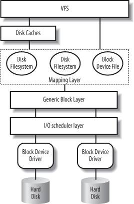 is the upper layer of the block device handling architecture, and it provides a common file model adopted by all filesystems supported by Linux. We have described at length the VFS layer in Chapter 12. The VFS function determines if the requested data is already available and, if necessary, how to perform the read operation. Sometimes there is no need to access the data on disk, because the kernel keeps in RAM the data most recently read fromor written toa block device. The disk cache mechanism is explained in Chapter 15, while details on how the VFS handles the disk operations and how it interfaces with the disk cache and the filesystems are given in Chapter 16. Let's assume that the kernel must read the data from the block device, thus it must determine the physical location of that data. To do this, the kernel relies on the mapping layer
, which typically executes two steps: It determines the block size of the filesystem including the file and computes the extent of the requested data in terms of file block numbers
. Essentially, the file is seen as split in many blocks, and the kernel determines the numbers (indices relative to the beginning of file) of the blocks containing the requested data. Next, the mapping layer invokes a filesystem-specific function that accesses the file's disk inode and determines the position of the requested data on disk in terms of logical block numbers. Essentially, the disk is seen as split in blocks, and the kernel determines the numbers (indices relative to the beginning of the disk or partition) corresponding to the blocks storing the requested data. Because a file may be stored in nonadjacent blocks on disk, a data structure stored in the disk inode maps each file block number to a logical block number.
We will see the mapping layer in action in Chapter 16, while we will present some typical disk-based filesystems in Chapter 18. The kernel can now issue the read operation on the block device. It makes use of the generic block layer
, which starts the I/O operations that transfer the requested data. In general, each I/O operation involves a group of blocks that are adjacent on disk. Because the requested data is not necessarily adjacent on disk, the generic block layer might start several I/O operations. Each I/O operation is represented by a "block I/O" (in short, "bio") structure, which collects all information needed by the lower components to satisfy the request. The generic block layer hides the peculiarities of each hardware block device, thus offering an abstract view of the block devices. Because almost all block devices are disks, the generic block layer also provides some general data structures that describe "disks" and "disk partitions." We will discuss the generic block layer and the bio structure in the section "The Generic Block Layer" later in this chapter. Below the generic block layer, the "I/O scheduler " sorts the pending I/O data transfer requests according to predefined kernel policies. The purpose of the scheduler is to group requests of data that lie near each other on the physical medium. We will describe this component in the section "The I/O Scheduler" later in this chapter. Finally, the block device drivers take care of the actual data transfer by sending suitable commands to the hardware interfaces of the disk controllers. We will explain the overall organization of a generic block device driver in the section "Block Device Drivers" later in this chapter.
As you can see, there are many kernel components that are concerned with data stored in block devices; each of them manages the disk data using chunks of different length:
The controllers of the hardware block devices transfer data in chunks of fixed length called "sectors." Therefore, the I/O scheduler and the block device drivers must manage sectors of data. The Virtual Filesystem, the mapping layer, and the filesystems group the disk data in logical units called "blocks." A block corresponds to the minimal disk storage unit inside a filesystem. As we will see shortly, block device drivers should be able to cope with "segments" of data: each segment is a memory pageor a portion of a memory pageincluding chunks of data that are physically adjacent on disk. The disk caches
work on "pages" of disk data, each of which fits in a page frame. The generic block layer glues together all the upper and lower components, thus it knows about sectors
, blocks, segments, and pages of data.
Even if there are many different chunks of data, they usually share the same physical RAM cells. For instance, Figure 14-2 shows the layout of a 4,096-byte page. The upper kernel components see the page as composed of four block buffers of 1,024 bytes each. The last three blocks of the page are being transferred by the block device driver, thus they are inserted in a segment covering the last 3,072 bytes of the page. The hard disk controller considers the segment as composed of six 512-byte sectors.
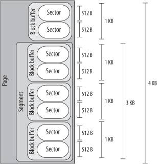
In this chapter we describe the lower kernel components that handle the block devicesgeneric block layer, I/O scheduler, and block device driversthus we focus our attention on sectors, blocks, and segments.
14.1.1. Sectors
To achieve acceptable performance, hard disks and similar devices transfer several adjacent bytes at once. Each data transfer operation for a block device acts on a group of adjacent bytes called a sector. In the following discussion, we say that groups of bytes are adjacent
when they are recorded on the disk surface in such a manner that a single seek operation can access them. Although the physical geometry of a disk is usually very complicated, the hard disk controller accepts commands that refer to the disk as a large array of sectors.
In most disk devices, the size of a sector is 512 bytes, although there are devices that use larger sectors (1,024 and 2,048 bytes). Notice that the sector should be considered as the basic unit of data transfer; it is never possible to transfer less than one sector, although most disk devices are capable of transferring several adjacent sectors at once.
In Linux, the size of a sector is conventionally set to 512 bytes; if a block device uses larger sectors, the corresponding low-level block device driver will do the necessary conversions. Thus, a group of data stored in a block device is identified on disk by its positionthe index of the first 512-byte sectorand its length as number of 512-byte sectors. Sector indices are stored in 32- or 64-bit variables of type sector_t.
14.1.2. Blocks
While the sector is the basic unit of data transfer for the hardware devices, the block is the basic unit of data transfer for the VFS and, consequently, for the filesystems. For example, when the kernel accesses the contents of a file, it must first read from disk a block containing the disk inode of the file (see the section "Inode Objects" in Chapter 12). This block on disk corresponds to one or more adjacent sectors, which are looked at by the VFS as a single data unit.
In Linux, the block size must be a power of 2 and cannot be larger than a page frame. Moreover, it must be a multiple of the sector size, because each block must include an integral number of sectors. Therefore, on 80 x 86 architecture, the permitted block sizes are 512, 1,024, 2,048, and 4,096 bytes.
The block size is not specific to a block device. When creating a disk-based filesystem, the administrator may select the proper block size. Thus, several partitions on the same disk might make use of different block sizes. Furthermore, each read or write operation issued on a block device file is a "raw" access that bypasses the disk-based filesystem; the kernel executes it by using blocks
of largest size (4,096 bytes).
Each block requires its own block buffer, which is a RAM memory area used by the kernel to store the block's content. When the kernel reads a block from disk, it fills the corresponding block buffer with the values obtained from the hardware device; similarly, when the kernel writes a block on disk, it updates the corresponding group of adjacent bytes on the hardware device with the actual values of the associated block buffer. The size of a block buffer always matches the size of the corresponding block.
Each buffer has a "buffer head" descriptor of type buffer_head. This descriptor contains all the information needed by the kernel to know how to handle the buffer; thus, before operating on each buffer, the kernel checks its buffer head. We will give a detailed explanation of all fields of the buffer head in Chapter 15; in the present chapter, however, we will only consider a few fields: b_page, b_data, b_blocknr, and b_bdev.
The b_page field stores the page descriptor address of the page frame that includes the block buffer. If the page frame is in high memory, the b_data field stores the offset of the block buffer inside the page; otherwise, it stores the starting linear address of the block buffer itself. The b_blocknr field stores the logical block number (i.e., the index of the block inside the disk partition). Finally, the b_bdev field identifies the block device that is using the buffer head (see the section "Block Devices" later in this chapter).
14.1.3. Segments
We know that each disk I/O operation consists of transferring the contents of some adjacent sectors fromor tosome RAM locations. In almost all cases, the data transfer is directly performed by the disk controller with a DMA operation (see the section "Direct Memory Access (DMA)" in Chapter 13). The block device driver simply triggers the data transfer by sending suitable commands to the disk controller; once the data transfer is finished, the controller raises an interrupt to notify the block device driver.
The data transferred by a single DMA operation must belong to sectors that are adjacent on disk. This is a physical constraint: a disk controller that allows DMA transfers to non-adjacent sectors would have a poor transfer rate, because moving a read/write head on the disk surface is quite a slow operation.
Older disk controllers support "simple" DMA operations only: in each such operation, data is transferred from or to memory cells that are physically contiguous in RAM. Recent disk controllers, however, may also support the so-called scatter-gather DMA transfers
: in each such operation, the data can be transferred from or to several noncontiguous memory areas.
For each scatter-gather DMA transfer, the block device driver must send to the disk controller:
The initial disk sector number and the total number of sectors to be transferred A list of descriptors of memory areas, each of which consists of an address and a length.
The disk controller takes care of the whole data transfer; for instance, in a read operation the controller fetches the data from the adjacent disk sectors and scatters it into the various memory areas.
To make use of scatter-gather DMA operations, block device drivers must handle the data in units called segments
. A segment is simply a memory pageor a portion of a memory pagethat includes the data of some adjacent disk sectors. Thus, a scatter-gather DMA operation may involve several segments at once.
Notice that a block device driver does not need to know about blocks, block sizes, and block buffers. Thus, even if a segment is seen by the higher levels as a page composed of several block buffers, the block device driver does not care about it.
As we'll see, the generic block layer can merge different segments if the corresponding page frames happen to be contiguous in RAM and the corresponding chunks of disk data are adjacent on disk. The larger memory area resulting from this merge operation is called physical segment.
Yet another merge operation is allowed on architectures that handle the mapping between bus addresses and physical addresses through a dedicated bus circuitry (the IO-MMU; see the section "Direct Memory Access (DMA)" in Chapter 13). The memory area resulting from this kind of merge operation is called hardware segment
. Because we will focus on the 80 x 86 architecture, which has no such dynamic mapping between bus addresses and physical addresses, we will assume in the rest of this chapter that hardware segments always coincide with physical segments
.
14.2. The Generic Block Layer
The generic block layer is a kernel component that handles the requests for all block devices in the system. Thanks to its functions, the kernel may easily:
Put data buffers in high memorythe page frame(s) will be mapped in the kernel linear address space only when the CPU must access the data, and will be unmapped right after. Implementwith some additional efforta "zero-copy" schema, where disk data is directly put in the User Mode address space without being copied to kernel memory first; essentially, the buffer used by the kernel for the I/O transfer lies in a page frame mapped in the User Mode linear address space of a process. Manage logical volumessuch as those used by LVM (the Logical Volume Manager) and RAID (Redundant Array of Inexpensive Disks): several disk partitions, even on different block devices, can be seen as a single partition. Exploit the advanced features of the most recent disk controllers, such as large onboard disk caches
, enhanced DMA capabilities, onboard scheduling of the I/O transfer requests, and so on.
14.2.1. The Bio Structure
The core data structure of the generic block layer is a descriptor of an ongoing I/O block device operation called bio. Each bio essentially includes an identifier for a disk storage areathe initial sector number and the number of sectors included in the storage areaand one or more segments describing the memory areas involved in the I/O operation. A bio is implemented by the bio data structure, whose fields are listed in Table 14-1.
Table 14-1. The fields of the bio structureType | Field | Description |
|---|
sector_t | bi_sector | First sector on disk of block I/O operation | struct bio * | bi_next | Link to the next bio in the request queue | struct block_device * | bi_bdev | Pointer to block device descriptor | unsigned long | bi_flags | Bio status flags | unsigned long | bi_rw | I/O operation flags | unsigned short | bi_vcnt | Number of segments in the bio's bio_vec array | unsigned short | bi_idx | Current index in the bio's bio_vec array of segments | unsigned short | bi_phys_segments | Number of physical segments of the bio after merging | unsigned short | bi_hw_segments | Number of hardware segments after merging | unsigned int | bi_size | Bytes (yet) to be transferred | unsigned int | bi_hw_front_size | Used by the hardware segment merge algorithm | unsigned int | bi_hw_back_size | Used by the hardware segment merge algorithm | unsigned int | bi_max_vecs | Maximum allowed number of segments in the bio's bio_vec array | struct bio_vec * | bi_io_vec | Pointer to the bio's bio_vec array of segments | bio_end_io_t * | bi_end_io | Method invoked at the end of bio's I/O operation | atomic_t | bi_cnt | Reference counter for the bio | void * | bi_private | Pointer used by the generic block layer and the I/O completion method of the block device driver | bio_destructor_t * | bi_destructor | Destructor method (usually bio_destructor()) invoked when the bio is being freed |
Each segment in a bio is represented by a bio_vec data structure, whose fields are listed in Table 14-2. The bi_io_vec field of the bio points to the first element of an array of bio_vec data structures, while the bi_vcnt field stores the current number of elements in the array.
Table 14-2. The fields of the bio_vec structureType | Field | Description |
|---|
struct page * | bv_page | Pointer to the page descriptor of the segment's page frame | unsigned int | bv_len | Length of the segment in bytes | unsigned int | bv_offset | Offset of the segment's data in the page frame |
The contents of a bio descriptor keep changing during the block I/O operation. For instance, if the block device driver cannot perform the whole data transfer with one scatter-gather DMA operation, the bi_idx field is updated to keep track of the first segment in the bio that is yet to be transferred. To iterate over the segments of a biostarting from the current segment at index bi_idxa device driver can execute the bio_for_each_segment macro.
When the generic block layer starts a new I/O operation, it allocates a new bio structure by invoking the bio_alloc( ) function. Usually, bios are allocated through the slab allocator, but the kernel also keeps a small memory pool of bios to be used when memory is scarce (see the section "Memory Pools" in Chapter 8). The kernel also keeps a memory pool for the bio_vec structuresafter all, it would not make sense to allocate a bio without being able to allocate the segment descriptors to be included in the bio. Correspondingly, the bio_put( ) function decrements the reference counter (bi_cnt) of a bio and, if the counter becomes zero, it releases the bio structure and the related bio_vec structures.
14.2.2. Representing Disks and Disk Partitions
A disk is a logical block device that is handled by the generic block layer. Usually a disk corresponds to a hardware block device such as a hard disk, a floppy disk, or a CD-ROM disk. However, a disk can be a virtual device built upon several physical disk partitions, or a storage area living in some dedicated pages of RAM. In any case, the upper kernel components operate on all disks
in the same way thanks to the services offered by the generic block layer.
A disk is represented by the gendisk object, whose fields are shown in Table 14-3.
Table 14-3. The fields of the gendisk objectType | Field | Description |
|---|
int | major | Major number of the disk | int | first_minor | First minor number associated with the disk | int | minors | Range of minor numbers associated with the disk | char [32] | disk_name | Conventional name of the disk (usually, the canonical name of the corresponding device file) | struct hd_struct ** | part | Array of partition descriptors for the disk | struct block_device_operations * | fops | Pointer to a table of block device methods | struct request_queue * | queue | Pointer to the request queue of the disk (see "Request Queue Descriptors" later in this chapter) | void * | private_data | Private data of the block device driver | sector_t | capacity | Size of the storage area of the disk (in number of sectors) | int | flags | Flags describing the kind of disk (see below) | char [64] | devfs_name | Device filename in the (nowadays deprecated) devfs
special filesystem | int | number | No longer used | struct device * | driverfs_dev | Pointer to the device object of the disk's hardware device (see the section "Components of the Device Driver Model" in Chapter 13) | struct kobject | kobj | Embedded kobject (see the section "Kobjects" in Chapter 13) | struct timer_rand_state * | random | Pointer to a data structure that records the timing of the disk's interrupts; used by the kernel built-in random number generator | int | policy | Set to 1 if the disk is read-only (write operations forbidden), 0 otherwise | atomic_t | sync_io | Counter of sectors written to disk, used only for RAID | unsigned long | stamp | Timestamp used to determine disk queue usage statistics | unsigned long | stamp_idle | Same as above | int | in_flight | Number of ongoing I/O operations | struct disk_stats * | dkstats | Statistics about per-CPU disk usage |
The flags field stores information about the disk. The most important flag is GENHD_FL_UP: if it is set, the disk is initialized and working. Another relevant flag is GENHD_FL_REMOVABLE, which is set if the disk is a removable support, such as a floppy disk or a CD-ROM.
The fops field of the gendisk object points to a block_device_operations table, which stores a few custom methods for crucial operations of the block device (see Table 14-4).
Table 14-4. The methods of the block devicesMethod | Triggers |
|---|
open | Opening the block device file | release | Closing the last reference to a block device file | ioctl | Issuing an ioctl( )
system call on the block device file (uses the big kernel lock
) | compat_ioctl | Issuing an ioctl( ) system call on the block device file (does not use the big kernel lock) | media_changed | Checking whether the removable media has been changed (e.g., floppy disk) | revalidate_disk | Checking whether the block device holds valid data |
Hard disks are commonly split into logical partitions
. Each block device file may represent either a whole disk or a partition inside the disk. For instance, a master EIDE disk might be represented by a device file /dev/hda having major number 3 and minor number 0; the first two partitions inside the disk might be represented by device files /dev/hda1 and /dev/hda2 having major number 3 and minor numbers 1 and 2, respectively. In general, the partitions inside a disk are characterized by consecutive minor numbers.
If a disk is split in partitions, their layout is kept in an array of hd_struct structures whose address is stored in the part field of the gendisk object. The array is indexed by the relative index of the partition inside the disk. The fields of the hd_struct descriptor are listed in Table 14-5.
Table 14-5. The fields of the hd_struct descriptorType | Field | Description |
|---|
sector_t | start_sect | Starting sector of the partition inside the disk | sector_t | nr_sects | Length of the partition (number of sectors) | struct kobject | kobj | Embedded kobject (see the section "Kobjects" in Chapter 13) | unsigned int | reads | Number of read operations issued on the partition | unsigned int | read_sectors | Number of sectors read from the partition | unsigned int | writes | Number of write operations issued on the partition | unsigned int | write_sectors | Number of sectors written into the partition | int | policy | Set to 1 if the partition is read-only, 0 otherwise | int | partno | The relative index of the partition inside the disk |
When the kernel discovers a new disk in the system (in the boot phase, or when a removable media is inserted in a drive, or when an external disk is attached at run-time), it invokes the alloc_disk( ) function, which allocates and initializes a new gendisk object and, if the new disk is split in several partitions, a suitable array of hd_struct descriptors. Then, it invokes the add_disk( ) function to insert the new gendisk descriptor into the data structures of the generic block layer (see the section "Device Driver Registration and Initialization" later in this chapter).
14.2.3. Submitting a Request
Let us describe the common sequence of steps executed by the kernel when submitting an I/O operation request to the generic block layer. We'll assume that the requested chunks of data are adjacent on disk and that the kernel has already determined their physical location.
The first step consists in executing the bio_alloc( ) function to allocate a new bio descriptor. Then, the kernel initializes the bio descriptor by setting a few fields:
The bi_sector field is set to the initial sector number of the data (if the block device is split in several partitions, the sector number is relative to the start of the partition). The bi_size field is set to the number of sectors covering the data. The bi_bdev field is set to the address of the block device descriptor (see the section "Block Devices" later in this chapter). The bi_io_vec field is set to the initial address of an array of bio_vec data structures, each of which describes a segment (memory buffer) involved in the I/O operation; moreover, the bi_vcnt field is set to the total number of segments in the bio. The bi_rw field is set with the flags of the requested operation. The most important flag specifies the data transfer direction: READ (0) or WRITE (1). The bi_end_io field is set to the address of a completion procedure that is executed whenever the I/O operation on the bio is completed.
Once the bio descriptor has been properly initialized, the kernel invokes the generic_make_request( ) function, which is the main entry point of the generic block layer. The function essentially executes the following steps:
Checks that bio->bi_sector does not exceed the number of sectors of the block device. If it does, the function sets the BIO_EOF flag of bio->bi_flags, prints a kernel error message, invokes the bio_endio() function, and terminates. bio_endio( ) updates the bi_size and bi_sector fields of the bio descriptor, and it invokes the bi_end_io bio's method. The implementation of the latter function essentially depends on the kernel component that has triggered the I/O data transfer; we will see some examples of bi_end_io methods in the following chapters. Gets the request queue q associated with the block device (see the section "Request Queue Descriptors" later in this chapter); its address can be found in the bd_disk field of the block device descriptor, which in turn is pointed to by the bio->bi_bdev field. Invokes block_wait_queue_running( ) to check whether the I/O scheduler currently in use is being dynamically replaced; in this case, the function puts the process to sleep until the new I/O scheduler is started (see the next section "The I/O Scheduler"). Invokes blk_partition_remap( ) to check whether the block device refers to a disk partition (bio->bi_bdev not equal to bio->bi_dev->bd_contains; see the section "Block Devices" later in this chapter). In this case, the function gets the hd_struct descriptor of the partition from the bio->bi_bdev field to perform the following substeps: Updates the read_sectors and reads fields, or the write_sectors and writes fields, of the hd_struct descriptor, according to the direction of data transfer. Adjusts the bio->bi_sector field so as to transform the sector number relative to the start of the partition to a sector number relative to the whole disk. Sets the bio->bi_bdev field to the block device descriptor of the whole disk (bio->bd_contains).
From now on, the generic block layer, the I/O scheduler, and the device driver forget about disk partitioning, and work directly with the whole disk. Invokes the q->make_request_fn method to insert the bio request in the request queue q.
We will discuss a typical implementation of the make_request_fn method in the section "Issuing a Request to the I/O Scheduler" later in this chapter.
|
14.3. The I/O Scheduler
Although block device drivers are able to transfer a single sector at a time, the block I/O layer does not perform an individual I/O operation for each sector to be accessed on disk; this would lead to poor disk performance, because locating the physical position of a sector on the disk surface is quite time-consuming. Instead, the kernel tries, whenever possible, to cluster several sectors and handle them as a whole, thus reducing the average number of head movements.
When a kernel component wishes to read or write some disk data, it actually creates a block device request. That request essentially describes the requested sectors and the kind of operation to be performed on them (read or write). However, the kernel does not satisfy a request as soon as it is createdthe I/O operation is just scheduled and will be performed at a later time. This artificial delay is paradoxically the crucial mechanism for boosting the performance of block devices. When a new block data transfer is requested, the kernel checks whether it can be satisfied by slightly enlarging a previous request that is still waiting (i.e., whether the new request can be satisfied without further seek operations). Because disks tend to be accessed sequentially, this simple mechanism is very effective.
Deferring requests complicates block device handling. For instance, suppose a process opens a regular file and, consequently, a filesystem driver wants to read the corresponding inode from disk. The block device driver puts the request on a queue, and the process is suspended until the block storing the inode is transferred. However, the block device driver itself cannot be blocked, because any other process trying to access the same disk would be blocked as well.
To keep the block device driver from being suspended, each I/O operation is processed asynchronously. In particular, block device drivers are interrupt-driven (see the section "Monitoring I/O Operations" in the previous chapter): the generic block layer invokes the I/O scheduler to create a new block device request or to enlarge an already existing one and then terminates. The block device driver, which is activated at a later time, invokes the strategy routine to select a pending request and satisfy it by issuing suitable commands to the disk controller. When the I/O operation terminates, the disk controller raises an interrupt and the corresponding handler invokes the strategy routine again, if necessary, to process another pending request.
Each block device driver maintains its own request queue, which contains the list of pending requests for the device. If the disk controller is handling several disks, there is usually one request queue for each physical block device. I/O scheduling is performed separately on each request queue, thus increasing disk performance.
14.3.1. Request Queue Descriptors
Each request queue is represented by means of a large request_queue data structure whose fields are listed in Table 14-6.
Table 14-6. The fields of the request queue descriptorType | Field | Description |
|---|
struct list_head | queue_head | List of pending requests | struct request * | last_merge | Pointer to descriptor of the request in the queue to be considered first for possible merging | elevator_t * | elevator | Pointer to the elevator object (see the later section "I/O Scheduling Algorithms") | struct request_list | rq | Data structure used for allocation of request descriptors | request_fn_proc * | request_fn | Method that implements the entry point of the strategy routine of the driver | merge_request_fn * | back_merge_fn | Method to check whether it is possible to merge a bio to the last request in the queue | merge_request_fn * | front_merge_fn | Method to check whether it is possible to merge a bio to the first request in the queue | merge_requests_fn * | merge_requests_fn | Method to attempt merging two adjacent requests in the queue | make_request_fn * | make_request_fn | Method invoked when a new request has to be inserted in the queue | prep_rq_fn * | prep_rq_fn | Method to build the commands to be sent to the hardware device to process this request | unplug_fn * | unplug_fn | Method to unplug the block device (see the section "Activating the Block Device Driver" later in the chapter) | merge_bvec_fn * | merge_bvec_fn | Method that returns the number of bytes that can be inserted into an existing bio when adding a new segment (usually undefined) | activity_fn * | activity_fn | Method invoked when a request is added to a queue (usually undefined) | issue_flush_fn * | issue_flush_fn | Method invoked when a request queue is flushed (the queue is emptied by processing all requests in a row) | struct timer_list | unplug_timer | Dynamic timer used to perform device plugging (see the later section "Activating the Block Device Driver") | int | unplug_thresh | If the number of pending requests in the queue exceeds this value, the device is immediately unplugged (default is 4) | unsigned long | unplug_delay | Time delay before device unplugging (default is 3 milliseconds) | struct work_struct | unplug_work | Work queue used to unplug the device (see the later section "Activating the Block Device Driver") | struct backing_dev_info | backing_dev_info | See the text following this table | void * | queuedata | Pointer to private data of the block device driver | void * | activity_data | Private data used by the activity_fn method | unsigned long | bounce_pfn | Page frame number above which buffer bouncing must be used (see the section "Submitting a Request" later in this chapter) | int | bounce_gfp | Memory allocation flags for bounce buffers | unsigned long | queue_flags | Set of flags describing the queue status | spinlock_t * | queue_lock | Pointer to request queue lock | struct kobject | kobj | Embedded kobject for the request queue | unsigned long | nr_requests | Maximum number of requests in the queue | unsigned int | nr_congestion_on | Queue is considered congested if the number of pending requests rises above this threshold | unsigned int | nr_congestion_off | Queue is considered not congested if the number of pending requests falls below this threshold | unsigned int | nr_batching | Maximum number (usually 32) of pending requests that can be submitted even when the queue is full by a special "batcher" process | unsigned short | max_sectors | Maximum number of sectors handled by a single request (tunable) | unsigned short | max_hw_sectors | Maximum number of sectors handled by a single request (hardware constraint) | unsigned short | max_phys_segments | Maximum number of physical segments handled by a single request | unsigned short | max_hw_segments | Maximum number of hardware segments handled by a single request (the maximum number of distinct memory areas in a scatter-gather DMA operation) | unsigned short | hardsect_size | Size in bytes of a sector | unsigned int | max_segment_size | Maximum size of a physical segment (in bytes) | unsigned long | seg_boundary_mask | Memory boundary mask for segment merging | unsigned int | dma_alignment | Alignment bitmap for initial address and length of DMA buffers (default 511) | struct blk_queue_tag * | queue_tags | Bitmap of free/busy tags (used for tagged requests) | atomic_t | refcnt | Reference counter of the queue | unsigned int | in_flight | Number of pending requests in the queue | unsigned int | sg_timeout | User-defined command time-out (used only by SCSI generic devices) | unsigned int | sg_reserved_size | Essentially unused | struct list_head | drain_list | Head of a list of requests temporarily delayed until the I/O scheduler is dynamically replaced |
Essentially, a request queue is a doubly linked list whose elements are request descriptors
(that is, request data structures; see the next section). The queue_head field of the request queue descriptor stores the head (the first dummy element) of the list, while the pointers in the queuelist field of the request descriptor link each request to the previous and next elements in the list. The ordering of the elements in the queue list is specific to each block device driver; the I/O scheduler offers, however, several predefined ways of ordering elements, which are discussed in the later section "The I/O Scheduler."
The backing_dev_info field is a small object of type backing_dev_info, which stores information about the I/O data flow traffic for the underlying hardware block device. For instance, it holds information about read-ahead and about request queue congestion state.
14.3.2. Request Descriptors
Each pending request for a block device is represented by a request descriptor, which is stored in the request data structure illustrated in Table 14-7.
Table 14-7. The fields of the request descriptorType | Field | Description |
|---|
struct list_head | queuelist | Pointers for request queue list | unsigned long | flags | Flags of the request (see below) | sector_t | sector | Number of the next sector to be transferred | unsigned long | nr_sectors | Number of sectors yet to be transferred in the whole request | unsigned int | current_nr_sectors | Number of sectors in the current segment of the current bio yet to be transferred | sector_t | hard_sector | Number of the next sector to be transferred | unsigned long | hard_nr_sectors | Number of sectors yet to be transferred in the whole request (updated by the generic block layer) | unsigned int | hard_cur_sectors | Number of sectors in the current segment of the current bio yet to be transferred (updated by the generic block layer) | struct bio * | bio | First bio in the request that has not been completely transferred | struct bio * | biotail | Last bio in the request list | void * | elevator_private | Pointer to private data for the I/O scheduler | int | rq_status | Request status: essentially, either RQ_ACTIVE or RQ_INACTIVE | struct gendisk * | rq_disk | The descriptor of the disk referenced by the request | int | errors | Counter for the number of I/O errors that occurred on the current transfer | unsigned long | start_time | Request's starting time (in jiffies) | unsigned short | nr_phys_segments | Number of physical segments of the request | unsigned short | nr_hw_segments | Number of hardware segments of the request | int | tag | Tag associated with the request (only for hardware devices supporting multiple outstanding data transfers) | char * | buffer | Pointer to the memory buffer of the current data transfer (NULL if the buffer is in high-memory) | int | ref_count | Reference counter for the request | request_queue_t * | q | Pointer to the descriptor of the request queue containing the request | struct request_list * | rl | Pointer to request_list data structure | struct completion * | waiting | Completion for waiting for the end of the data transfers (see the section "Completions" in Chapter 5) | void * | special | Pointer to data used when the request includes a "special" command to the hardware device | unsigned int | cmd_len | Length of the commands in the cmd field | unsigned char [] | cmd | Buffer containing the pre-built commands prepared by the request queue's prep_rq_fn method | unsigned int | data_len | Usually, the length of data in the buffer pointed to by the data field | void * | data | Pointer used by the device driver to keep track of the data to be transferred | unsigned int | sense_len | Length of buffer pointed to by the sense field (0 if the sense field is NULL) | void * | sense | Pointer to buffer used for output of sense commands | unsigned int | timeout | Request's time-out | struct request_pm_state * | pm | Pointer to a data structure used for power-management commands |
Each request consists of one or more bio structures. Initially, the generic block layer creates a request including just one bio. Later, the I/O scheduler may "extend" the request either by adding a new segment to the original bio, or by linking another bio structure into the request. This is possible when the new data is physically adjacent to the data already in the request. The bio field of the request descriptor points to the first bio structure in the request, while the biotail field points to the last bio. The rq_for_each_bio macro implements a loop that iterates over all bios included in a request.
Several fields of the request descriptor may dynamically change. For instance, as soon as the chunks of data referenced in a bio have all been transferred, the bio field is updated so that it points to the next bio in the request list. Meanwhile, new bios can be added to the tail of the request list, so the biotail field may also change.
Several other fields of the request descriptor are modified either by the I/O scheduler or the device driver while the disk sectors are being transferred. For instance, the nr_sectors field stores the number of sectors yet to be transferred in the whole request, while the current_nr_sectors field stores the number of sectors yet to be transferred in the current bio.
The flags field stores a large number of flags, which are listed in Table 14-8. The most important one is, by far, REQ_RW, which determines the direction of the data transfer.
Table 14-8. The flags of the request descriptorFlag | Description |
|---|
REQ_RW | Direction of data transfer: READ (0) or WRITE (1) | REQ_FAILFAST | Requests says to not retry the I/O operation in case of error | REQ_SOFTBARRIER | Request acts as a barrier for the I/O scheduler | REQ_HARDBARRIER | Request acts as a barrier for the I/O scheduler and the device driverit should be processed after older requests and before newer ones | REQ_CMD | Request includes a normal read or write I/O data transfer | REQ_NOMERGE | Request should not be extended or merged with other requests | REQ_STARTED | Request is being processed | REQ_DONTPREP | Do not invoke the prep_rq_fn request queue's method to prepare in advance the commands to be sent to the hardware device | REQ_QUEUED | Request is taggedthat is, it refers to a hardware device that can manage many outstanding data transfers at the same time | REQ_PC | Request includes a direct command to be sent to the hardware device | REQ_BLOCK_PC | Same as previous flag, but the command is included in a bio | REQ_SENSE | Request includes a "sense" request command (for SCSI and ATAPI devices) | REQ_FAILED | Set when a sense or direct command in the request did not work as expected | REQ_QUIET | Request says to not generate kernel messages in case of I/O errors | REQ_SPECIAL | Request includes a special command for the hardware device (e.g., drive reset) | REQ_DRIVE_CMD | Request includes a special command for IDE disks | REQ_DRIVE_TASK | Request includes a special command for IDE disks | REQ_DRIVE_TASKFILE | Request includes a special command for IDE disks | REQ_PREEMPT | Request replaces the current request in front of the queue (only for IDE disks) | REQ_PM_SUSPEND | Request includes a power-management command to suspend the hardware device | REQ_PM_RESUME | Request includes a power-management command to awaken the hardware device | REQ_PM_SHUTDOWN | Request includes a power-management command to switch off the hardware device | REQ_BAR_PREFLUSH | Request includes a "flush queue" command to be sent to the disk controller | REQ_BAR_POSTFLUSH | Request includes a "flush queue" command, which has been sent to the disk controller |
14.3.2.1. Managing the allocation of request descriptors
The limited amount of free dynamic memory may become, under very heavy loads and high disk activity, a bottleneck for processes that want to add a new request into a request queue q. To cope with this kind of situation, each request_queue descriptor includes a request_list data structure, which consists of:
A pointer to a memory pool of request descriptors (see the section "Memory Pools" in Chapter 8). Two counters for the number of requests descriptors allocated for READ and WRITE requests, respectively. Two flags indicating whether a recent allocation for a READ or WRITE request, respectively, failed. Two wait queues storing the processes sleeping for available READ and WRITE request descriptors, respectively. A wait queue for the processes waiting for a request queue to be flushed (emptied).
The blk_get_request( ) function tries to get a free request descriptor from the memory pool of a given request queue; if memory is scarce and the memory pool is exhausted, the function either puts the current process to sleep orif the kernel control path cannot blockreturns NULL. If the allocation succeeds, the function stores in the rl field of the request descriptor the address of the request_list data structure of the request queue. The blk_put_request( ) function releases a request descriptor; if its reference counter becomes zero, the descriptor is given back to the memory pool from which it was taken.
14.3.2.2. Avoiding request queue congestion
Each request queue has a maximum number of allowed pending requests. The nr_requests field of the request descriptor stores the maximum number of allowed pending requests for each data transfer direction. By default, a queue has at most 128 pending read requests and 128 pending write requests. If the number of pending read (write) requests exceeds nr_requests, the queue is marked as full by setting the QUEUE_FLAG_READFULL (QUEUE_FLAG_WRITEFULL) flag in the queue_flags field of the request queue descriptor, and blockable processes trying to add requests for that data transfer direction are put to sleep in the corresponding wait queue of the request_list data structure.
A filled-up request queue impacts negatively on the system's performance, because it forces many processes to sleep while waiting for the completion of I/O data transfers. Thus, if the number of pending requests for a given direction exceeds the value stored in the nr_congestion_on field of the request descriptor (by default, 113), the kernel regards the queue as congested and tries to slow down the creation rate of the new requests. A congested request queue becomes uncongested when the number of pending requests falls below the value of the nr_congestion_off field (by default, 111). The blk_congestion_wait( ) function puts the current process to sleep until any request queue becomes uncongested or a time-out elapses.
14.3.3. Activating the Block Device Driver
As we saw earlier, it's expedient to delay activation of the block device driver in order to increase the chances of clustering requests for adjacent blocks. The delay is accomplished through a technique known as device plugging and unplugging. As long as a block device driver is plugged, the device driver is not activated even if there are requests to be processed in the driver's queues.
The blk_plug_device( ) function plugs a block deviceor more precisely, a request queue serviced by some block device driver. Essentially, the function receives as an argument the address q of a request queue descriptor. It sets the QUEUE_FLAG_PLUGGED bit in the q->queue_flags field; then, it restarts the dynamic timer embedded in the q->unplug_timer field.
The blk_remove_plug( ) function unplugs a request queue q: it clears the QUEUE_FLAG_PLUGGED flag and cancels the execution of the q->unplug_timer dynamic timer. This function can be explicitly invoked by the kernel when all mergeable requests "in sight" have been added to the queue. Moreover, the I/O scheduler unplugs a request queue if the number of pending requests in the queue exceeds the value stored in the unplug_thres field of the request queue descriptor (by default, 4).
If a device remains plugged for a time interval of length q->unplug_delay (usually 3 milliseconds), the dynamic timer activated by blk_plug_device( ) elapses, thus the blk_unplug_timeout( ) function is executed. As a consequence, the kblockd
kernel thread servicing the kblockd_workqueue work queue is awakened (see the section "Work Queues" in Chapter 4). This kernel thread executes the function whose address is stored in the q->unplug_work data structurethat is, the blk_unplug_work( ) function. In turn, this function invokes the q->unplug_fn method of the request queue, which is usually implemented by the generic_unplug_device( ) function. The generic_unplug_device( ) function takes care of unplugging the block device: first, it checks whether the queue is still active; then, it invokes blk_remove_plug( ); and finally, it executes the strategy routinerequest_fn methodto start processing the next request in the queue (see the section "Device Driver Registration and Initialization" later in this chapter).
14.3.4. I/O Scheduling Algorithms
When a new request is added to a request queue, the generic block layer invokes the I/O scheduler to determine that exact position of the new element in the queue. The I/O scheduler tries to keep the request queue sorted sector by sector. If the requests to be processed are taken sequentially from the list, the amount of disk seeking is significantly reduced because the disk head moves in a linear way from the inner track to the outer one (or vice versa) instead of jumping randomly from one track to another. This heuristic is reminiscent of the algorithm used by elevators when dealing with requests coming from different floors to go up or down. The elevator moves in one direction; when the last booked floor is reached in one direction, the elevator changes direction and starts moving in the other direction. For this reason, I/O schedulers are also called elevators.
Under heavy load, an I/O scheduling algorithm that strictly follows the order of the sector numbers is not going to work well. In this case, indeed, the completion time of a data transfer strongly depends on the physical position of the data on the disk. Thus, if a device driver is processing requests near the top of the queue (lower sector numbers), and new requests with low sector numbers are continuously added to the queue, then the requests in the tail of the queue can easily starve. I/O scheduling algorithms are thus quite sophisticated.
Currently, Linux 2.6 offers four different types of I/O schedulersor elevatorscalled "Anticipatory," "Deadline," "CFQ (Complete Fairness Queueing)," and "Noop (No Operation)." The default elevator used by the kernel for most block devices is specified at boot time with the kernel parameter elevator=<name>, where <name> is one of the following: as, deadline, cfq, and noop. If no boot time argument is given, the kernel uses the "Anticipatory" I/O scheduler. Anyway, a device driver can replace the default elevator with another one; a device driver can also define its custom I/O scheduling algorithm, but this is very seldom done.
Furthermore, the system administrator can change at runtime the I/O scheduler for a specific block device. For instance, to change the I/O scheduler used in the master disk of the first IDE channel, the administrator can write an elevator name into the /sys/block/hda/queue/scheduler file of the sysfs
special filesystem (see the section "The sysfs Filesystem" in Chapter 13).
The I/O scheduler algorithm used in a request queue is represented by an elevator object of type elevator_t; its address is stored in the elevator field of the request queue descriptor. The elevator object includes several methods covering all possible operations of the elevator: linking and unlinking the elevator to a request queue, adding and merging requests to the queue, removing requests from the queue, getting the next request to be processed from the queue, and so on. The elevator object also stores the address of a table including all information required to handle the request queue. Furthermore, each request descriptor includes an elevator_private field that points to an additional data structure used by the I/O scheduler to handle the request.
Let us now briefly describe the four I/O scheduling algorithms, from the simplest one to the most sophisticated one. Be warned that designing an I/O scheduler is much like designing a CPU scheduler (see Chapter 7): the heuristics and the values of the adopted constants are the result of an extensive amount of testing and benchmarking.
Generally speaking, all algorithms make use of a dispatch queue, which includes all requests sorted according to the order in which the requests should be processed by the device driverthe next request to be serviced by the device driver is always the first element in the dispatch queue. The dispatch queue is actually the request queue rooted at the queue_head field of the request queue descriptor. Almost all algorithms also make use of additional queues to classify and sort requests. All of them allow the device driver to add bios to existing requests and, if necessary, to merge two "adjacent" requests.
14.3.4.1. The "Noop" elevator
This is the simplest I/O scheduling algorithm. There is no ordered queue: new requests are always added either at the front or at the tail of the dispatch queue, and the next request to be processed is always the first request in the queue.
14.3.4.2. The "CFQ" elevator
The main goal of the "Complete Fairness Queueing" elevator is ensuring a fair allocation of the disk I/O bandwidth among all the processes that trigger the I/O requests. To achieve this result, the elevator makes use of a large number of sorted queuesby default, 64that store the requests coming from the different processes. Whenever a requested is handed to the elevator, the kernel invokes a hash function that converts the thread group identifier of the current process (usually it corresponds to the PID, see the section "Identifying a Process" in Chapter 3) into the index of a queue; then, the elevator inserts the new request at the tail of this queue. Therefore, requests coming from the same process are always inserted in the same queue.
To refill the dispatch queue, the elevator essentially scans the I/O input queues in a round-robin fashion, selects the first nonempty queue, and moves a batch of requests from that queue into the tail of the dispatch queue.
14.3.4.3. The "Deadline" elevator
Besides the dispatch queue, the "Deadline" elevator makes use of four queues. Two of themthe sorted queues
include the read and write requests, respectively, ordered according to their initial sector numbers. The other twothe deadline queues
include the same read and write requests sorted according to their "deadlines." These queues are introduced to avoid request starvation
, which occurs when the elevator policy ignores for a very long time a request because it prefers to handle other requests that are closer to the last served one. A request deadline is essentially an expire timer that starts ticking when the request is passed to the elevator. By default, the expire time of read requests is 500 milliseconds, while the expire time for write requests is 5 secondsread requests are privileged over write requests because they usually block the processes that issued them. The deadline ensures that the scheduler looks at a request if it's been waiting a long time, even if it is low in the sort.
When the elevator must replenish the dispatch queue, it first determines the data direction of the next request. If there are both read and write requests to be dispatched, the elevator chooses the "read" direction, unless the "write" direction has been discarded too many times (to avoid write requests starvation).
Next, the elevator checks the deadline queue relative to the chosen direction: if the deadline of the first request in the queue is elapsed, the elevator moves that request to the tail of the dispatch queue; it also moves a batch of requests taken from the sorted queue, starting from the request following the expired one. The length of this batch is longer if the requests happen to be physically adjacent on disks, shorter otherwise.
Finally, if no request is expired, the elevator dispatches a batch of requests starting with the request following the last one taken from the sorted queue. When the cursor reaches the tail of the sorted queue, the search starts again from the top ("one-way elevator").
14.3.4.4. The "Anticipatory" elevator
The "Anticipatory" elevator is the most sophisticated I/O scheduler algorithm offered by Linux. Basically, it is an evolution of the "Deadline" elevator, from which it borrows the fundamental mechanism: there are two deadline queues and two sorted queues; the I/O scheduler keeps scanning the sorted queues, alternating between read and write requests, but giving preference to the read ones. The scanning is basically sequential, unless a request expires. The default expire time for read requests is 125 milliseconds, while the default expire time for write requests is 250 milliseconds. The elevator, however, follows some additional heuristics:
In some cases, the elevator might choose a request behind the current position in the sorted queue, thus forcing a backward seek of the disk head. This happens, typically, when the seek distance for the request behind is less than half the seek distance of the request after the current position in the sorted queue. The elevator collects statistics about the patterns of I/O operations triggered by every process in the system. Right after dispatching a read request that comes from some process P, the elevator checks whether the next request in the sorted queue comes from the same process P. If so, the next request is dispatched immediately. Otherwise, the elevator looks at the collected statistics about process P: if it decides that process P will likely issue another read request soon, then it stalls for a short period of time (by default, roughly 7 milliseconds). Thus, the elevator might anticipate a read request coming from process P that is "close" on disk to the request just dispatched.
14.3.5. Issuing a Request to the I/O Scheduler
As seen in the section "Submitting a Request" earlier in this chapter, the generic_make_request( ) function invokes the make_request_fn method of the request queue descriptor to transmit a request to the I/O scheduler. This method is usually implemented by the _ _make_request( ) function; it receives as its parameters a request_queue descriptor q and a bio descriptor bio, and it performs the following operations:
Invokes the blk_queue_bounce( ) function to set up a bounce buffer, if required (see later). If a bounce buffer was created, the _ _make_request( ) function operates on it rather than on the original bio. Invokes the I/O scheduler function elv_queue_empty( ) to check whether there are pending requests in the request queuenotice that the dispatch queue might be empty, but other queues of the I/O scheduler might contain pending requests. If there are no pending requests, it invokes the blk_plug_device( ) function to plug the request queue (see the section "Activating the Block Device Driver" earlier in this chapter), and jumps to step 5. Here the request queue includes pending requests. Invokes the elv_merge( ) I/O scheduler function to check whether the new bio can be merged inside an existing request. The function may return three possible values: ELEVATOR_NO_MERGE: the bio cannot be included in an already existing request: in that case, the function jumps to step 5. ELEVATOR_BACK_MERGE: the bio might be added as the last bio of some request req: in that case, the function invokes the q->back_merge_fn method to check whether the request can be extended. If not, the function jumps to step 5. Otherwise it inserts the bio descriptor at the tail of the req's list and updates the req's fields. Then, it tries to merge the request with a following request (the new bio might fill a hole between the two requests). ELEVATOR_FRONT_MERGE: the bio can be added as the first bio of some request req: in that case, the function invokes the q->front_merge_fn method to check whether the request can be extended. If not, it jumps to step 5. Otherwise, it inserts the bio descriptor at the head of the req's list and updates the req's fields. Then, the function tries to merge the request with the preceding request.
The bio has been merged inside an already existing request. Jumps to step 7 to terminate the function. Here the bio must be inserted in a new request. Allocates a new request descriptor. If there is no free memory, the function suspends the current process, unless the BIO_RW_AHEAD flag in bio->bi_rw is set, which means that the I/O operation is a read-ahead (see Chapter 16); in this case, the function invokes bio_endio( ) and terminates: the data transfer will not be executed. For a description of bio_endio( ), see step 1 of generic_make_request( ) in the earlier section "Submitting a Request." Initializes the fields of the request descriptor. In particular: Initializes the various fields that store the sector numbers, the current bio, and the current segment according to the contents of the bio descriptor. Sets the REQ_CMD flag in the flags field (this is a normal read or write operation). If the page frame of the first bio segment is in low memory, it sets the buffer field to the linear address of that buffer. Sets the rq_disk field with the bio->bi_bdev->bd_disk address. Inserts the bio in the request list. Sets the start_time field to the value of jiffies.
All done. Before terminating, however, it checks whether the BIO_RW_SYNC flag in bio->bi_rw is set. If so, it invokes generic_unplug_device( ) on the request queue to unplug the driver (see the section "Activating the Block Device Driver" earlier in this chapter).
If the request queue was not empty before invoking _ _make_request( ), either the request queue is already unplugged, or it will be unplugged soonbecause each plugged request queue q with pending requests has a running q->unplug_timer dynamic timer. On the other hand, if the request queue was empty, the _ _make_request( ) function plugs it. Sooner (on exiting from _ _make_request( ), if the BIO_RW_SYNC bio flag is set) or later (in the worst case, when the unplug timer decays), the request queue will be unplugged. In any case, eventually the strategy routine of the block device driver will take care of the requests in the dispatch queue (see the section "Device Driver Registration and Initialization" earlier in this chapter).
14.3.5.1. The blk_queue_bounce( ) function
The blk_queue_bounce( ) function looks at the flags in q->bounce_gfp and at the threshold in q->bounce_pfn to determine whether buffer bouncing
might be required. This happens when some of the buffers in the request are located in high memory and the hardware device is not able to address them.
Older DMA for ISA buses only handled 24-bit physical addresses. In this case, the buffer bouncing threshold is set to 16 MB, that is, to page frame number 4096. Block device drivers, however, do not usually rely on buffer bouncing when dealing with older devices; rather, they prefer to directly allocate the DMA buffers in the ZONE_DMA memory zone.
If the hardware device cannot cope with buffers in high memory, the function checks whether some of the buffers in the bio must really be bounced. In this case, it makes a copy of the bio descriptor, thus creating a bounce bio; then, for each segment's page frame having number equal to or greater than q->bounce_pfn, it performs the following steps:
Allocates a page frame in the ZONE_NORMAL or ZONE_DMA memory zone, according to the allocation flags. Updates the bv_page field of the segment in the bounce bio so that it points to the descriptor of the new page frame. If bio->bio_rw specifies a write operation, it invokes kmap( ) to temporarily map the high memory page in the kernel address space, copies the high memory page onto the low memory page, and invokes kunmap( ) to release the mapping.
The blk_queue_bounce( ) function then sets the BIO_BOUNCED flag in the bounce bio, initializes a specific bi_end_io method for the bounce bio, and finally stores in the bi_private field of the bounce bio the pointer to the original bio. When the I/O data transfer on the bounce bio terminates, the function that implements the bi_end_io method copies the data to the high memory buffer (only for a read operation) and releases the bounce bio.
14.4. Block Device Drivers
Block device drivers are the lowest component of the Linux block subsystem. They get requests from I/O scheduler, and do whatever is required to process them.
Block device drivers are, of course, integrated within the device driver model described in the section "The Device Driver Model" in Chapter 13. Therefore, each of them refers to a device_driver descriptor; moreover, each disk handled by the driver is associated with a device descriptor. These descriptors, however, are rather generic: the block I/O subsystem must store additional information for each block device in the system.
14.4.1. Block Devices
A block device driver may handle several block devices. For instance, the IDE device driver can handle several IDE disks, each of which is a separate block device. Furthermore, each disk is usually partitioned, and each partition can be seen as a logical block device. Clearly, the block device driver must take care of all VFS system calls issued on the block device files associated with the corresponding block devices.
Each block device is represented by a block_device descriptor, whose fields are listed in Table 14-9.
Table 14-9. The fields of the block device descriptorType | Field | Description |
|---|
dev_t | bd_dev | Major and minor numbers of the block device | struct inode * | bd_inode | Pointer to the inode of the file associated with the block device in the bdev
filesystem | int | bd_openers | Counter of how many times the block device has been opened | struct semaphore | bd_sem | Semaphore protecting the opening and closing of the block device | struct semaphore | bd_mount_sem | Semaphore used to forbid new mounts on the block device | struct list_head | bd_inodes | Head of a list of inodes of opened block device files for this block device | void * | bd_holder | Current holder of block device descriptor | int | bd_holders | Counter for multiple settings of the bd_holder field | struct block_device * | bd_contains | If block device is a partition, it points to the block device descriptor of the whole disk; otherwise, it points to this block device descriptor | unsigned | bd_block_size | Block size | struct hd_struct * | bd_part | Pointer to partition descriptor (NULL if this block device is not a partition) | unsigned | bd_part_count | Counter of how many times partitions included in this block device have been opened | int | bd_invalidated | Flag set when the partition table on this block device needs to be read | struct gendisk * | bd_disk | Pointer to gendisk structure of the disk underlying this block device | struct list_head * | bd_list | Pointers for the block device descriptor list | struct backing_dev_info * | bd_inode_back ing_dev_info | Pointer to a specialized backing_dev_info descriptor for this block device (usually NULL) | unsigned long | bd_private | Pointer to private data of the block device holder |
All block device descriptors are inserted in a global list, whose head is represented by the all_bdevs variable; the pointers for list linkage are in the bd_list field of the block device descriptor.
If the block device descriptor refers to a disk partition, the bd_contains field points to the descriptor of the block device associated with the whole disk, while the bd_part field points to the hd_struct partition descriptor (see the section "Representing Disks and Disk Partitions" earlier in this chapter). Otherwise, if the block device descriptor refers to a whole disk, the bd_contains field points to the block device descriptor itself, and the bd_part_count field records how many times the partitions on the disk have been opened.
The bd_holder field stores a linear address representing the holder of the block device. The holder is not the block device driver that services the I/O data transfers of the device; rather, it is a kernel component that makes use of the device and has exclusive, special privileges (for instance, it can freely use the bd_private field of the block device descriptor). Typically, the holder of a block device is the filesystem mounted over it. Another common case occurs when a block device file is opened for exclusive access: the holder is the corresponding file object.
The bd_claim( ) function sets the bd_holder field with a specified address; conversely, the bd_release( ) function resets the field to NULL. Be aware, however, that the same kernel component can invoke bd_claim( ) many times; each invocation increases the bd_holders field. To release the block device, the kernel component must invoke bd_release( ) a corresponding number of times.
Figure 14-3 refers to a whole disk and illustrates how the block device descriptors are linked to the other main data structures of the block I/O subsystem.
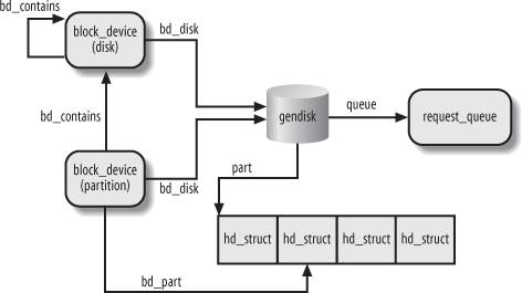
14.4.1.1. Accessing a block device
When the kernel receives a request for opening a block device file, it must first determine whether the device file is already open. In fact, if the file is already open, the kernel must not create and initialize a new block device descriptor; rather, it should update the already existing block device descriptor. To complicate life, block device files that have the same major and minor numbers but different pathnames are viewed by the VFS as different files, although they really refer to the same block device. Therefore, the kernel cannot determine whether a block device is already in use by simply checking for the existence in the inode cache
of an object for a block device file.
The relationship between a major and minor number and the corresponding block device descriptor is maintained through the bdev
special filesystem (see the section "Special Filesystems" in Chapter 12). Each block device descriptor is coupled with a bdev special file: the bd_inode field of the block device descriptor points to the corresponding bdev inode; conversely, such an inode encodes both the major and minor numbers of the block device and the address of the corresponding descriptor.
The bdget( ) function receives as its parameter the major and minor numbers of a block device: It looks up in the bdev filesystem the associated inode; if such inode does not exist, the function allocates a new inode and new block device descriptor. In any case, the function returns the address of the block device descriptor corresponding to given major and minor numbers.
Once the block device descriptor for a block device has been found, the kernel can determine whether the block device is currently in use by checking the value of the bd_openers field: if it is positive, the block device is already in use (possibly by means of a different device file). The kernel also maintains a list of inode objects relative to opened block device files. This list is rooted at the bd_inodes field of the block device descriptor; the i_devices field of the inode object stores the pointers for the previous and next element in this list.
14.4.2. Device Driver Registration and Initialization
Let's now explain the essential steps involved in setting up a new device driver for a block device. Clearly, the description that follows is very succinct, nevertheless it could be useful to understand how and when the main data structures used by the block I/O subsystem are initialized.
We silently omit many steps required for all kinds of device drivers and already mentioned in Chapter 13. For example, we skip all steps required for registering the driver itself (see the section "The Device Driver Model" in Chapter 13). Usually, the block device belongs to a standard bus architecture such as PCI or SCSI, and the kernel offers helper functions that, as a side effect, register the driver in the device driver model.
14.4.2.1. Defining a custom driver descriptor
First of all, the device driver needs a custom descriptor foo of type foo_dev_t holding the data required to drive the hardware device. For every device, the descriptor will store information such as the I/O ports used to program the device, the IRQ line of the interrupts raised by the device, the internal status of the device, and so on. The descriptor must also include a few fields required by the block I/O subsystem:
 struct foo_dev_t {
     [...]
     spinlock_t lock;
     struct gendisk *gd;
     [...]
 } foo;
The lock field is a spin lock used to protect the fields of the foo descriptor; its address is often passed to kernel helper functions, which can thus protect the data structures of the block I/O subsystem specific to the driver. The gd field is a pointer to the gendisk descriptor that represents the whole block device (disk) handled by this driver.
Reserving the major number
The device driver must reserve a major number for its own purposes. Traditionally, this is done by invoking the register_blkdev( ) function:
 err = register_blkdev(FOO_MAJOR, "foo");
 if (err) goto error_major_is_busy;
This function is very similar to register_chrdev( ) presented in the section "Assigning Device Numbers" in Chapter 13: it reserves the major number FOO_MAJOR and associates the name foo to it. Notice that there is no way to allocate a subrange of minor numbers, because there is no analog of register_chrdev_region( ); moreover, no link is established between the reserved major number and the data structures of the driver. The only visible effect of register_blkdev( ) is to include a new item in the list of registered major numbers in the /proc/devices special file.
14.4.2.2. Initializing the custom descriptor
All the fields of the foo descriptor must be initialized properly before making use of the driver. To initialize the fields related to the block I/O subsystem, the device driver could execute the following instructions:
 spin_lock_init(&foo.lock);
 foo.gd = alloc_disk(16);
 if (!foo.gd) goto error_no_gendisk;
The driver initializes the spin lock, then allocates the disk descriptor. As shown earlier in Figure 14-3, the gendisk structure is crucial for the block I/O subsystem, because it references many other data structures. The alloc_disk( ) function allocates also the array that stores the partition descriptors of the disk. The argument of the function is the number of hd_struct elements in the array; the value 16 means that the driver can support disks containing up to 15 partitions (partition 0 is not used).
14.4.2.3. Initializing the gendisk descriptor
Next, the driver initializes some fields of the gendisk descriptor:
 foo.gd->private_data = &foo;
 foo.gd->major = FOO_MAJOR;
 foo.gd->first_minor = 0;
 foo.gd->minors = 16;
 set_capacity(foo.gd, foo_disk_capacity_in_sectors);
 strcpy(foo.gd->disk_name, "foo");
 foo.gd->fops = &foo_ops;
The address of the foo descriptor is saved in the private_data of the gendisk structure, so that low-level driver functions invoked as methods by the block I/O subsystem can quickly find the driver descriptorthis improves efficiency if the driver can handle more than one disk at a time. The set_capacity( ) function initializes the capacity field with the size of the disk in 512-byte sectorsthis value is likely determined by probing the hardware and asking about the disk parameters.
14.4.2.4. Initializing the table of block device methods
The fops field of the gendisk descriptor is initialized with the address of a custom table of block device methods (see Table 14-4 earlier in this chapter). Quite likely, the foo_ops table of the device driver includes functions specific to the device driver. As an example, if the hardware device supports removable disks, the generic block layer may invoke the media_changed method to check whether the disk is changed since the last mount or open operation on the block device. This check is usually done by sending some low-level commands to the hardware controller, thus the implementation of the media_changed method is always specific to the device driver.
Similarly, the ioctl method is only invoked when the generic block layer does not know how to handle some ioctl command. For instance, the method is typically invoked when an ioctl( )
system call asks about the disk geometry
, that is, the number of cylinders, tracks, sectors, and heads used by the disk. Thus, the implementation of this method is specific to the device driver.
14.4.2.5. Allocating and initializing a request queue
Our brave device driver designer might now set up a request queue that will collect the requests waiting to be serviced. This can be easily done as follows:
 foo.gd->rq = blk_init_queue(foo_strategy, &foo.lock);
 if (!foo.gd->rq) goto error_no_request_queue;
 blk_queue_hardsect_size(foo.gd->rd, foo_hard_sector_size);
 blk_queue_max_sectors(foo.gd->rd, foo_max_sectors);
 blk_queue_max_hw_segments(foo.gd->rd, foo_max_hw_segments);
 blk_queue_max_phys_segments(foo.gd->rd, foo_max_phys_segments);
The blk_init_queue( ) function allocates a request queue descriptor and initializes many of its fields with default values. It receives as its parameters the address of the device descriptor's spin lockfor the foo.gd->rq->queue_lock fieldand the address of the strategy routine of the device driverfor the foo.gd->rq->request_fn field; see the next section; "The Strategy Routine." The blk_init_queue( ) function also initializes the foo.gd->rq->elevator field, forcing the driver to use the default I/O scheduler algorithm. If the device driver wants to use a different elevator, it may later override the address in the elevator field.
Next, some helper functions set various fields of the request queue descriptor with the proper values for the device driver (look at Table 14-6 for the similarly named fields).
14.4.2.6. Setting up the interrupt handler
As described in the section "I/O Interrupt Handling" in Chapter 4, the driver needs to register the IRQ line for the device. This can be done as follows:
 request_irq(foo_irq, foo_interrupt,
             SA_INTERRUPT|SA_SHIRQ, "foo", NULL);
The foo_interrupt() function is the interrupt handler for the device; we discuss some of its peculiarities in the section "The Interrupt Handler" later in this chapter).
14.4.2.7. Registering the disk
Finally, all the device driver's data structures are ready: the last step of the initialization phase consists of "registering" and activating the disk. This can be achieved simply by executing:
add_disk(foo.gd);
The add_disk( ) function receives as its parameter the address of the gendisk descriptor, and essentially executes the following operations:
Sets the GENHD_FL_UP flag of gd->flags. Invokes kobj_map() to establish the link between the device driver and the device's major number with its associated range of minor numbers (see the section "Character Device Drivers" in Chapter 13; be warned that in this case the kobject mapping domain
is represented by the bdev_map variable). Registers the kobject included in the gendisk descriptor in the device driver model as a new device serviced by the device driver (e.g., /sys/block/foo). Scans the partition table included in the disk, if any; for each partition found, properly initializes the corresponding hd_struct descriptor in the foo.gd->part array. Also registers the partitions in the device driver model (e.g., /sys/block/foo/foo1). Registers the kobject embedded in the request queue descriptor in the device driver model (e.g., /sys/block/foo/queue).
Once add_disk( ) returns, the device driver is actively working. The function that carried on the initialization phase terminates; the strategy routine and the interrupt handler take care of each request passed to the device driver by the I/O scheduler.
14.4.3. The Strategy Routine
The strategy routine is a functionor a group of functionsof the block device driver that interacts with the hardware block device to satisfy the requests collected in the dispatch queue. The strategy routine is invoked by means of the request_fn method of the request queue descriptorthe foo_strategy( ) function in the example carried on in the previous section. The I/O scheduler layer passes to this function the address q of the request queue descriptor.
As we'll see, the strategy routine is usually started after inserting a new request in an empty request queue. Once activated, the block device driver should handle all requests in the queue and terminate when the queue is empty.
A naïve implementation of the strategy routine could be the following: for each element in the dispatch queue, remove it from the queue, interact with the block device controller to service the request, and wait until the data transfer completes. Then proceed with the next request in the dispatch queue.
Such an implementation is not very efficient. Even assuming that the data can be transferred using DMA, the strategy routine must suspend itself while waiting for I/O completion. This means that the strategy routine should execute on a dedicated kernel thread (we don't want to penalize an unrelated user process, do we?). Moreover, such a driver would not be able to support modern disk controllers that can process multiple I/O data transfers at a time.
Therefore, most block device drivers adopt the following strategy:
The strategy routine starts a data transfer for the first request in the queue and sets up the block device controller so that it raises an interrupt when the data transfer completes. Then the strategy routine terminates. When the disk controller raises the interrupt, the interrupt handler invokes the strategy routine again (often directly, sometimes by activating a work queue). The strategy routine either starts another data transfer for the current request or, if all the chunks of data of the request have been transferred, removes the request from the dispatch queue and starts processing the next request.
Requests can be composed of several bios, which in turn can be composed of several segments. Basically, block device drivers make use of DMA in two ways:
The driver sets up a different DMA transfer to service each segment in each bio of the request The driver sets up a single scatter-gather DMA transfer to service all segments in all bios of the request
Ultimately, the design of the strategy routine of the device drivers depends on the characteristics of the block controller. Each physical block device is inherently different from all others (for example, a floppy driver groups blocks in disk tracks and transfers a whole track in a single I/O operation), so making general assumptions on how a device driver should service a request is meaningless.
In our example, the foo_strategy( ) strategy routine could execute the following actions:
Gets the current request from the dispatch queue by invoking the elv_next_request( ) I/O scheduler helper function. If the dispatch queue is empty, the strategy routine returns:
 req = elv_next_request(q);
 if (!req) return;
Executes the blk_fs_request macro to check whether the REQ_CMD flag of the request is set, that is, whether the request contains a normal read or write operation:
 if (!blk_fs_request(req))
     goto handle_special_request;
If the block device controller supports scatter-gather DMA, it programs the disk controller so as to perform the data transfer for the whole request and to raise an interrupt when the transfer completes. The blk_rq_map_sg( ) helper function returns a scatter-gather list that can be immediately used to start the transfer. Otherwise, the device driver must transfer the data segment by segment. In this case, the strategy routine executes the rq_for_each_bio and bio_for_each_segment macros, which walk the list of bios and the list of segments inside each bio, respectively:
 rq_for_each_bio(bio, rq)
     bio_for_each_segment(bvec, bio, i) {
         /* transfer the i-th segment bvec */
         local_irq_save(flags);
         addr = kmap_atomic(bvec->bv_page, KM_BIO_SRC_IRQ);
         foo_start_dma_transfer(addr+bvec->bv_offset, bvec->bv_len);
         kunmap_atomic(bvec->bv_page, KM_BIO_SRC_IRQ);
         local_irq_restore(flags);
     }
The kmap_atomic( ) and kunmap_atomic( ) functions are required if the data to be transferred can be in high memory. The foo_start_dma_transfer( ) function programs the hardware device so as to start the DMA transfer and to raise an interrupt when the I/O operation completes.
14.4.4. The Interrupt Handler
The interrupt handler of a block device driver is activated when a DMA transfer terminates. It should check whether all chunks of data in the request have been transferred. If so, the interrupt handler invokes the strategy routine to process the next request in the dispatch queue. Otherwise, the interrupt handler updates the field of the request descriptor and invokes the strategy routine to process the data transfer yet to be performed.
A typical fragment of the interrupt handler of our foo device driver is the following:
 irqreturn_t foo_interrupt(int irq, void *dev_id, struct pt_regs *regs)
 {
     struct foo_dev_t *p = (struct foo_dev_t *) dev_id;
     struct request_queue *rq = p->gd->rq;
        [...]
     if (!end_that_request_first(rq, uptodate, nr_sectors)) {
         blkdev_dequeue_request(rq);
         end_that_request_last(rq);
     }
     rq->request_fn(rq);
        [...]
     return IRQ_HANDLED;
 }
The job of ending a request is split in two functions called end_that_request_first( ) and end_that_request_last( ).
The end_that_request_first( ) function receives as arguments a request descriptor, a flag indicating if the DMA data transfer completed successfully, and the number of sectors transferred in the DMA transfer (the end_that_request_chunk( ) function is similar, but it receives the number of bytes transferred instead of the number of sectors). Essentially, the function scans the bios in the request and the segments inside each bio, then updates the fields of the request descriptor in such a way to:
Set the bio field so that it points to the first unfinished bio in the request. Set the bi_idx of the unfinished bio so that it points to the first unfinished segment. Set the bv_offset and bv_len fields of the unfinished segment so that they specify the data yet to be transferred.
The function also invokes bio_endio( ) on each bio that has been completely transferred.
The end_that_request_first( ) function returns 0 if all chunks of data in the request have been transferred; otherwise, it returns 1. If the returned value is 1, the interrupt handler restarts the strategy routine, which thus continues processing the same request. Otherwise, the interrupt handler removes the request from the request queue (typically by using blkdev_dequeue_request( )), invokes the end_that_request_last( ) helper function, and restarts the strategy routine to process the next request in the dispatch queue.
The end_that_request_last( ) function updates some disk usage statistics, removes the request descriptor from the dispatch queue of the rq->elevator I/O scheduler, wakes up any process sleeping in the waiting completion of the request descriptor, and releases that descriptor.
|
14.5. Opening a Block Device File
We conclude this chapter by describing the steps performed by the VFS when opening a block device file.
The kernel opens a block device file every time that a filesystem is mounted over a disk or partition, every time that a swap partition is activated, and every time that a User Mode process issues an open( )
system call on a block device file. In all cases, the kernel executes essentially the same operations: it looks for the block device descriptor (possibly allocating a new descriptor if the block device is not already in use), and sets up the file operation methods for the forthcoming data transfers.
In the section "VFS Handling of Device Files" in Chapter 13, we described how the dentry_open( ) function customizes the methods of the file object when a device file is opened. In this case, the f_op field of the file object is set to the address of the def_blk_fops table, whose content is shown in Table 14-10.
Table 14-10. The default block device file operations (def_blk_fops table)Method | Function |
|---|
open | blkdev_open( ) | release | blkdev_close( ) | llseek | block_llseek( ) | read | generic_file_read( ) | write | blkdev_file_write( ) | aio_read | generic_file_aio_read( ) | aio_write | blkdev_file_aio_write( ) | mmap | generic_file_mmap( ) | fsync | block_fsync( ) | ioctl | block_ioctl( ) | compat-ioctl | compat_blkdev_ioctl( ) | readv | generic_file_readv( ) | writev | generic_file_write_nolock( ) | sendfile | generic_file_sendfile( ) |
Here we are only concerned with the open method, which is invoked by the dentry_open( ) function. The blkdev_open( ) function receives as its parameters inode and filp, which store the addresses of the inode and file objects respectively; the function essentially executes the following steps:
Executes bd_acquire(inode ) to get the address bdev
of the block device descriptor. In turn, this function receives the inode object address and performs the following steps: Checks whether the inode->i_bdev field of the inode object is not NULL; if it is, the block device file has been opened already, and this field stores the address of the corresponding block descriptor. In this case, the function increases the usage counter of the inode->i_bdev->bd_inode inode of the bdev special filesystem associated with the block device, and returns the address inode->i_bdev of the descriptor. Here the block device file has not been opened yet. Executes bdget(inode->i_rdev) to get the address of the block device descriptor corresponding to the major and minor number of the block device file (see the section "Block Devices" earlier in this chapter). If the descriptor does not already exist, bdget( ) allocates it; notice however that the descriptor might already exist, for instance because the block device is already being accessed by means of another block device file. Stores the block device descriptor address in inode->i_bdev, so as to speed up future opening operations on the same block device file. Sets the inode->i_mapping field with the value of the corresponding field in the bdev inode. This is the pointer to the address space object, which will be explained in the section "The address_space Object" in Chapter 15. Inserts inode into the list of opened inodes of the block device descriptor rooted at bdev->bd_inodes. Returns the address bdev of the descriptor.
Sets the filp->i_mapping field with the value of inode->i_mapping (see step 1(d) above). Gets the address of the gendisk descriptor relative to this block device:
disk = get_gendisk(bdev->bd_dev, &part);
If the block device being opened is a partition, the function also returns its index in the part local variable; otherwise, part is set to zero. The get_gendisk( ) function simply invokes kobj_lookup( ) on the bdev_map kobject mapping domain
passing the major and minor number of the device (see also the section "Device Driver Registration and Initialization" earlier in this chapter). If bdev->bd_openers is not equal to zero, the block device has already been opened. Checks the bdev->bd_contains field: If it is equal to bdev, the block device is a whole disk: invokes the bdev->bd_disk->fops->open block device method, if defined, then checks the bdev->bd_invalidated field and invokes, if necessary, the rescan_partitions( ) functions (see comments on steps 6a and 6c later). If it not equal to bdev, the block device is a partition: increases the bdev->bd_contains->bd_part_count counter.
Then, jumps to step 8. Here the block device is being accessed for the first time. Initializes bdev->bd_disk with the address disk of the gendisk descriptor. If the block device is a whole disk (part is zero), it executes the following substeps: If defined, it executes the disk->fops->open block device method: it is a custom function defined by the block device driver to perform any specific last-minute initialization. Gets from the hardsect_size field of the disk->queue request queue the sector size in bytes, and uses this value to set properly the bdev->bd_block_size and bdev->bd_inode->i_blkbits fields. Sets also the bdev->bd_inode->i_size field with the size of the disk computed from disk->capacity. If the bdev->bd_invalidated flag is set, it invokes rescan_partitions( ) to scan the partition table and update the partition descriptors. The flag is set by the check_disk_change block device method, which applies only to removable devices.
Otherwise if the block device is a partition (part is not zero), it executes the following substeps: Invokes bdget( ) againthis time passing the disk->first_minor minor numberto get the address whole of the block descriptor for the whole disk. Repeats steps from 3 to 6 for the block device descriptor of the whole disk, thus initializing it if necessary. Sets bdev->bd_contains to the address of the descriptor of the whole disk. Increases whole->bd_part_count to account for the new open operation on the partition of the disk. Sets bdev->bd_part with the value in disk->part[part-1]; it is the address of the hd_struct descriptor of the partition. Also, executes kobject_get(&bdev->bd_part->kobj) to increase the reference counter of the partition. As in step 6b, sets the inode fields that specify size and sector size of the partition.
Increases the bdev->bd_openers counter. If the block device file is being opened in exclusive mode (O_EXCL flag in filp->f_flags set), it invokes bd_claim(bdev, filp) to set the holder of the block device (see the section "Block Devices" earlier in this chapter). In case of errorblock device has already an holderit releases the block device descriptor and returns the error code -EBUSY. Terminates by returning 0 (success).
Once the blkdev_open( ) function terminates, the open( ) system call proceeds as usual. Every future system call issued on the opened file will trigger one of the default block device file operations. As we will see in Chapter 16, each data transfer to or from the block device is effectively implemented by submitting requests to the generic block layer.
|
|
|
|
|

 LINUX
LINUX 
 Books
Books

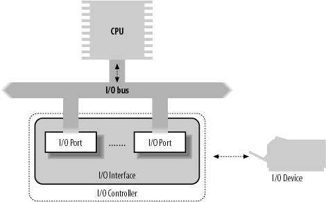
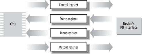
 ]
]