Управление памятью: Алгоритмы и реализация на C/C++
Механизм управления памятью
Механизм Versus Policy
Доступ и манипуляция памятью предполагает большой обьем работы.
Необходимо убедиться в том , что выделяемая память существует физически.
Если механизм защиты в порядке ,
проверка будет выполнена самим процессором.
Защита памяти - это встроенная опция любой многопользовательской операционной системой.
Если используется виртуальная память ,
нужно выделить определенное количество секторов диска для решения этой задачи.
Усилий нужно предпринять больше , чем вы думаете ,
и все это должно быть выполнено в комплексе.
| Note |
On the Intel platform, if the memory subsystem's data structures are set up incorrectly, the processor will perform what is known as a triple fault. A double fault occurs on Intel hardware when an exception occurs while the processor is already trying to handle an exception. A triple fault occurs when the double-fault handler fails and the machine is placed into the SHUTDOWN cycle. Typically, an Intel machine will reset when it encounters this type of problem.
|
For the sake of execution speed, processor manufacturers give their chips the capacity to carry out advanced memory management chores. This allows operating system vendors to effectively push most of the tedious, repetitive work down to the processor where the various error checks can be performed relatively quickly. This also has the side effect of anchoring the operating system vendor to the hardware platform, to an extent.
The performance gains, however, are well worth the lost portability. If an operating system were completely responsible for implementing features like paging and segmentation, it would be noticeably slower than one that took advantage of the processor's built-in functionality. Imagine trying to play a graphics-intensive, real-time game like Quake 3 on an operating system that manually protected memory; the game would just not be playable.
| Note |
You might be asking if I can offer a quantitative measure of how much slower an operating system would be. I will admit I have been doing a little arm waving. According to a 1993 paper by Wahbe, Lucco, et al. (see the "References" section), they were able to isolate modules of code in an application using a technique they labeled as sandboxing. This technique incurred a 4% increase in execution speed. You can imagine what would happen if virtual memory and access privilege schemes were added to such a mechanism.
|
| Note |
Back when Dave Cutler's brainchild, Windows NT, came out, there was a lot of attention given to the operating system's Hardware Abstraction Layer (HAL). The idea was that the majority of the operating system could be insulated from the hardware that it ran on by a layer of code located in the basement. This was instituted to help counter the hardware dependency issue that I mentioned a minute ago. To Dave's credit, NT actually did run on a couple of traditionally UNIX-oriented hardware platforms. This included Digital's Alpha processor and the MIPS RISC processor. The problem was that Microsoft couldn't get a number of its higher-level technologies, like DCOM, to run on anything but Intel. So much for an object technology based on a binary standard!
|
The solution that favors speed always wins. I was told by a former Control Data engineer that when Seymour Cray was designing the 6600, he happened upon a new chip that was quicker than the one he was currently using. The problem was that it made occasional computational errors. Seymour implemented a few slick work-arounds and went with the new chip. The execs wanted to stay out of Seymour's way and not disturb the maestro, as Seymour was probably the most valuable employee Control Data had. Unfortunately, they also had warehouses full of the original chips. They couldn't just throw out the old chips; they had to find a use for them. This problem gave birth to the CDC 3300, a slower and less expensive version of the 6600.
My point: Seymour went for the faster chip, even though it was less reliable.
Speed rules.
The result of this tendency is that every commercial operating system in existence has its memory management services firmly rooted in data structures and protocols dictated by the hardware. Processors provide a collection of primitives for manipulating memory. They constitute the mechanism side of the equation. It is up to the operating system to decide if it will even use a processor's memory management mechanisms and, if so, how it will use them. Operating systems constitute the policy side of the equation.
In this chapter, I will examine computer hardware in terms of how it offers a mechanism to access and manipulate memory.
Иерархия памяти
When someone uses the term "memory," they are typically referring to the data storage provided by dedicated chips located on the motherboard. The storage these chips provide is often referred to as Random Access Memory (RAM), main memory, and primary storage. Back in the iron age, when mainframes walked the earth, it was called the core. The storage provided by these chips is volatile, which is to say that data in the chips is lost when the power is switched off.
There are various types of RAM:
Dynamic RAM (DRAM) has to be recharged thousands of times each second. Synchronous DRAM (SDRAM) is refreshed at the clock speed at which the processor runs the most efficiently. Static RAM (SRAM) does not need to be refreshed like DRAM, and this makes it much faster. Unfortunately, SRAM is also much more expensive than DRAM and is used sparingly. SRAM tends to be used in processor caches and DRAM tends to be used for wholesale memory. Finally, there's Video RAM (VRAM), which is a region of memory used by video hardware. In the next chapter, there is an example that demonstrates how to produce screen messages by manipulating VRAM.
Recent advances in technology and special optimizations implemented by certain manufacturers have led to a number of additional acronyms. Here are a couple of them:
DDR SDRAM stands for Double Data Rate Synchronous Dynamic Random Access Memory. With DDR SDRAM, data is read on both the rising and the falling of the system clock tick, basically doubling the bandwidth normally available. RDRAM is short for Rambus DRAM, a high-performance version of DRAM sold by Rambus that can transfer data at 800 MHz. Enhanced Synchronous DRAM (ESDRAM), manufactured by Enhanced Memory Systems, provides a way to replace SRAM with cheaper SDRAM.
A bit is a single binary digit (i.e., a 1 or a 0). A bit in a RAM chip is basically a cell structure that is made up of, depending on the type of RAM, a certain configuration of transistors and capacitors. Each cell is a digital switch that can either be on or off (i.e., 1 or 0). These cells are grouped into 8-bit units call bytes. The byte is the fundamental unit for measuring the amount of memory provided by a storage device. In the early years, hardware vendors used to implement different byte sizes. One vendor would use a 6-bit byte and another would use a 16-bit byte. The de facto standard that everyone seems to abide by today, however, is the 8-bit byte.
There is a whole set of byte-based metrics to specify the size of a memory region:
1 byte = 8 bits
1 word = 2 bytes
1 double word = 4 bytes
1 quad word = 8 bytes
1 octal word = 8 bytes
1 paragraph = 16 bytes
1 kilobyte (KB) = 1,024 bytes
1 megabyte (MB) = 1,024KB = 1,048,576 bytes
1 gigabyte (GB) = 1,024MB = 1,073,741,824 bytes
1 terabyte (TB) = 1,024GB = 1,099,511,627,776 bytes
1 petabyte (PB) = 1,024TB = 1,125,899,906,842,624 bytes
| Note |
In the 1980s, having a megabyte of DRAM was a big deal. Kids used to bug their parents for 16KB memory upgrades so their Atari 400s could play larger games. At the time, having only a megabyte wasn't a significant problem because engineers tended to program in assembly code and build very small programs. In fact, this 1981 quote is often attributed to Bill Gates: "640K ought to be enough for anybody."
|
Today, most development machines have at least 128MB of DRAM. In 2002, having 256MB seems to be the norm. Ten years from now, a gigabyte might be the standard amount of DRAM (if we are still using DRAM). Hopefully, someone will not quote me.
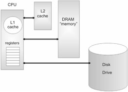
RAM is not the only place to store data, and this is what leads us to the memory hierarchy. The range of different places that can be used to store information can be ordered according to their proximity to the processor. This ordering produces the following hierarchy:
-
Registers
-
Cache
-
RAM
-
Disk storage
The primary distinction between these storage areas is their memory latency, or lag time. Storage closer to the processor takes less time to access than storage that is further away. The latency experienced in accessing data on a hard drive is much greater than the latency that occurs when the processor accesses memory in its cache. For example, DRAM latency tends to be measured in nanoseconds. Disk drive latency, however, tends to be measured in milliseconds! (See Figure 1.1 on the following page.)
Registers are small storage spaces that are located within the processor itself. Registers are a processor's favorite workspace. Most of the processor's day-to-day work is performed on data in the registers. Moving data from one register to another is the single most expedient way to move data.
Software engineers designing compilers will jump through all sorts of hoops just to keep variables and constants in the registers. Having a large number of registers allows more of a program's state to be stored within the processor itself and cut down on memory latency. The MIPS64 processor has 32, 64-bit, general-purpose registers for this very reason. The Itanium, Intel's next generation 64-bit chip, goes a step further and has literally hundreds of registers.
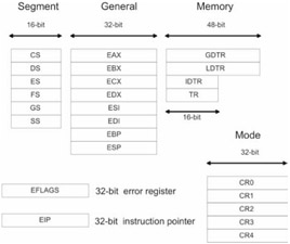
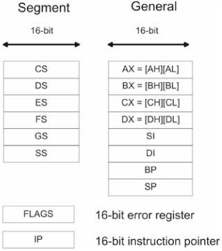
The Intel Pentium processor has a varied set of registers (see Figure 1.2). There are six, 16-bit, segment registers (CS, DS, ES, FS, GS, SS). There are eight, 32-bit, general-purpose registers (EAX, EBX, ECX, EDX, ESI, EDI, EBP, ESP). There is also a 32-bit error flag register (EFLAGS) to signal problems and a 32-bit instruction pointer (EIP).
Advanced memory management functions are facilitated by four system registers (GDTR, LDTR, IDTR, TR) and five mode control registers (CR0, CR1, CR2, CR3, CR4). The usage of these registers will be explained in the next few sections.
| Note |
It is interesting to note how the Pentium's collection of registers has been constrained by historical forces. The design requirement demanding backward compatibility has resulted in the Pentium having only a few more registers than the 8086.
|
A cache provides temporary storage that can be accessed quicker than DRAM. By placing computationally intensive portions of a program in the cache, the processor can avoid the overhead of having to continually access DRAM. The savings can be dramatic. There are different types of caches. An L1 cache is a storage space that is located on the processor itself. An L2 cache is typically an SRAM chip outside of the processor (for example, the Intel Pentium 4 ships with a 256 or 512KB L2 Advanced Transfer Cache).
| Note |
If you are attempting to optimize code that executes in the cache, you should avoid unnecessary function calls. A call to a distant function requires the processor to execute code that lies outside the cache. This causes the cache to reload. This is one reason why certain C compilers offer you the option of generating inline functions. The other side of the coin is that a program that uses inline functions will be much larger than one that does not. The size-versus-speed trade-off is a balancing act that rears its head all over computer science.
|
Disk storage is the option of last resort. Traditionally, disk space has been used to create virtual memory. Virtual memory is memory that is simulated by using disk space. In other words, portions of memory, normally stored in DRAM, are written to disk so that the amount of memory the processor can access is greater than the actual amount of physical memory. For example, if you have 10MB of DRAM and you use 2MB of disk space to simulate memory, the processor can then access 12MB of virtual memory.
| Note |
A recurring point that I will make throughout this book is the high cost of disk input/output. As I mentioned previously, the latency for accessing disk storage is on the order of milliseconds. This is a long time from the perspective of a processor. The situation is analogous to making a pizza run from a remote cabin in North Dakota. If you are lucky, you have a frozen pizza in your freezer/cache and it will only take 30 minutes to heat up. If you are not lucky, you will have to call the pizza delivery guy (i.e., access the data from disk storage) and wait for five hours as he makes the 150-mile trek to your cabin.
|
Using virtual memory is like making a deal with the devil. Sure, you will get lots of extra memory, but you will pay an awful cost in terms of performance. Disk I/O involves a whole series of mandatory actions, some of which are mechanical. It is estimated that paging on Windows accounts for roughly 10% of execution time. Managing virtual memory requires a lot of bookkeeping on the part of the processor. I will discuss the precise nature of this bookkeeping in a later section.
Disk storage has always been cheaper than RAM. Back in the 1960s when 8KB of RAM was a big investment, using the disk to create virtual memory probably made sense. Today, however, the cost discrepancy between DRAM and disk drives is not as significant as it was back then. Buying a machine with 512MB of SDRAM is not unheard of. It could be that virtual memory will become a complete relic or implemented as some sort of emergency safeguard.
Адресные линии и шины
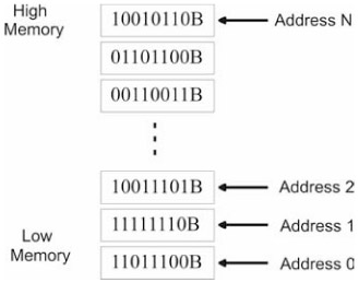
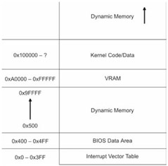
Each byte in DRAM is assigned a unique numeric identifier called an address, just like houses on a street. An address is an integer value. The first byte in memory is assigned an address of zero. The region of memory near address zero is known as the bottom of memory, or low memory. The region of memory near the final byte is known as high memory. The number of physical (i.e., DRAM) bytes that a processor is capable of addressing is known as the processor's physical address space. (See Figure 1.3.)
The physical address space of a processor specifies the potential number of bytes that can be addressed, not the actual number of physical bytes present. People normally don't want to spend the money necessary to populate the entire physical address space with DRAM chips. Buying 4GB of DRAM is still usually reserved for high-end enterprise servers.
The physical address space of a processor is determined by the number of address lines that it has. Address lines are a set of wires connecting the processor to its DRAM chips. Each address line specifies a single bit in the address of a given byte. For example, the Intel Pentium has 32 address lines. This means that each byte is assigned a 32-bit address so that its address space consists of 232 addressable bytes (4GB). The 8088 had 20 address lines, so it was capable of addressing 220, or 1,048,576, bytes.
| Note |
If virtual memory is enabled on the Pentium 4, there is a way to enable four additional address lines using what is known as Physical Address Extension (PAE). This allows the Pentium processor's physical address space to be defined by 36 address lines, which translates into an address space of 236 bytes (64GB).
|
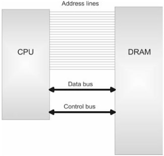
To access and update physical memory, the processor uses a control bus and a data bus. A bus is a collection of related wires that connect the processor to a hardware subsystem. The control bus is used to indicate if the processor wants to read from memory or write to memory. The data bus is used to ferry data back and forth between the processor and memory. (See Figure 1.4.)
When the processor reads from memory, the following steps are performed:
-
The processor places the address of the byte to be read on the address lines.
-
The processor sends the read signal on the control bus.
-
The DRAM chip(s) return the byte specified on the data bus.
When the processor writes to memory, the following steps are performed:
-
The processor places the address of the byte to be written on the address lines.
-
The processor sends the write signal on the control bus.
-
The processor sends the byte to be written to memory on the data bus.
This description is somewhat of an oversimplification. For example, the Pentium processor reads and writes data 4 bytes at a time. This is one reason why the Pentium is called a 32-bit chip. The processor will refer to its 32-bit payload using the address of the first byte (i.e., the byte with the lowest address). Nevertheless, I think the general operation is clear.
Архитектура Intel Pentium
You have seen how a processor reads and writes bytes to memory. However, most processors also support two advanced memory management mechanisms: segmentation and paging.
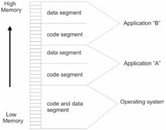
Segmentation is instituted by breaking up a computer's address space into specific regions, known as segments. Using segmentation is a way to isolate areas of memory so that programs cannot interfere with one another. Segmentation affords what is known as memory protection. It is possible to institute memory segmentation without protection, but there are really no advantages to such a scheme.
Under a segmentation scheme that enforces memory protection, each application is assigned at least one segment. Large applications often have several segments. In addition, the operating system will also have its own custom set of segments. Segments are assigned a specific set of access writes so that policies can be created with regard to who can update what. Typically, the operating system code segments will execute with the highest privilege and applications will be loaded into segments with less authority.
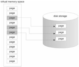
Paging is a way to implement virtual memory. The physical memory provided by DRAM and disk storage, which is allocated to simulate DRAM, are merged together into one big amorphous collection of bytes. The total number of bytes that a processor is capable of addressing, if paging is enabled, is known as its virtual address space.
The catch to all this is that the address of a byte in this artificial/virtual address space is no longer the same as the address that the processor places on the address bus. This means that translation data structures and code will have to be established in order to map a byte in the virtual address space to a physical byte (regardless of whether that byte happens to be in DRAM or on disk).
When the necessary paging constructs have been activated, the virtual memory space is divided into smaller regions called pages. If the operating system decides that it is running low on physical memory, it will take pages that are currently stored in physical memory and write them to disk. If segmentation is being used, bookkeeping will have to be performed in order to match a given page of memory with the segment that owns it. All of the accounting work is done in close conjunction with the processor so that the performance hit associated with disk I/O can be kept to a minimum.
| Note |
When pages of data are stored in physical memory (i.e., DRAM), they are placed in page-sized slots that are known as page frames. In addition to keeping track of individual pages, most operating systems also monitor page frame usage. The number of page frames is usually much smaller than the number of pages, so it is in the best interest of the operating system to carefully manage this precious commodity.
|
| Note |
It is possible to use paging without using disk space. But in this case, paging transforms into a hybrid form of segmentation that deals with 4KB regions of memory.
|
Because Intel's Pentium class of processors is easily accessible, I decided to use the Pentium to help illustrate segmentation and paging. I would love to demonstrate theory with a MIPS64 processor, but I can't afford an SGI server (sigh). Being inexpensive is one of the primary reasons for Intel's continued success. Hackers, like me, who couldn't afford an Apple IIe back in the 1980s were left scrounging for second-hand Intel boxes. There were thousands of people who had to make this kind of financial decision. So, in a sense, the proliferation of Intel into the workplace was somewhat of a grass roots movement.
The Pentium class of processors is descended from a long line of popular CPUs:
| Note |
When the IBM PC came out in 1981, it shipped with a 4.77 MHz 8088. Without a doubt, mainframe developers were overjoyed. This was because the PC gave them a place of their own. In those days, the standard dummy terminals didn't do anything more than shuttle a data buffer back and forth to a mainframe. In addition, an engineer had little or no control over when, or how, his code would be run. The waiting could be agonizing. Tom Petty was right. Bribing a sysop with pizza could occasionally speed things up, but the full court grovel got tiring after a while. With an IBM PC, an engineer finally had a build machine that was open all night with no waiting.
|
In an attempt to keep their old customers, Intel has gone to great lengths to make their 32-bit processors backward compatible with the previous 16-bit models. As testimony to Intel's success, I can boot my laptop with a DOS 6.22 boot disk and run most of my old DOS applications (including Doom and Duke Nukem).
A product of the requirement for backward compatibility is that the Pentium chip operates in a number of different modes. Each mode dictates how the processor will interpret machine instructions and how it can access memory. Specifically, the Pentium is capable of operating in four modes:
System management mode and virtual 8086 mode are both special-purpose modes of operation that are only used under special circumstances. I will focus primarily on the first two modes of operation: real mode and protected mode. In addition, I will investigate how each of these modes support segmentation and paging.
Having the processor operate in different modes is not a feature limited to the Intel platform. The MIPS64 processor, for example, also operates in four modes:
-
Kernel mode
-
User mode
-
Debug mode
-
Supervisor mode
Real Mode Operation
The first IBM PC ran strictly in real mode. Furthermore, all 32-bit Intel computers also start in real mode when they are booted. This sort of provides a least common denominator behavior that backward compatibility depends upon.
Real mode operating systems tend to be very small (i.e., less than 128KB) because they rely on the BIOS to provide an interface to the hardware. This allows them to easily fit on a 1.44MB floppy diskette. Virus protection rescue disks rely on this fact, as do system repair disks. I have also bought drive partitioning software that can be run from a boot disk.
In real mode, the general-purpose registers we saw earlier in Figure 1.2 are truncated into 16-bit registers, as are the error flag and instruction pointer registers. The real mode register setup is displayed in Figure 1.7.
As you can see, the "E" prefix has been removed from the register names. In addition, each of the 16-bit general registers, AX, CX, DX, and EX, can be manipulated in terms of two 8-bit registers. For example, the AX register can be seen as the combination of the AH and AL registers. The AH register refers to the high byte in AX, and the AL register refers to the low byte in AX.
| Note |
The memory and mode registers shown in Figure 1.2 are still visible in real mode. They still exist if the processor is a 32-bit class CPU but they have no significance or use in real mode. The only exception to this rule is if you are trying to switch to protected mode.
|
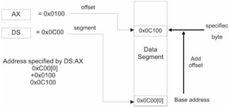
A machine in real mode can address 1MB of DRAM. This implies that only 20 address lines are used in real mode. The address of a byte in memory, for a processor real mode, is formed by adding an offset address to a segment address. The result of the sum is always a 20-bit value (remember this fact; it is important), which confirms our suspicion that there are 20 address lines.
The address formed by the sum of the segment and offset addresses corresponds directly to the value that is placed on the processor's address lines. Now you can get a better idea of why they call it "real" mode. The address of a byte in real mode maps directly to a "real" byte in physical memory.
An address is denoted, in Intel assembly language, by a segment:offset pair. For example, if a byte is located in segment 0x8200 and is situated at an offset of 0x0100, the address of this byte is specified as:
Sometimes, for reasons that I will explain later, this is also written as:
The real mode address resolution process is displayed in Figure 1.8.
Segment addresses denote a particular memory segment and are always stored in one of the 16-bit segment registers. Specifically, a segment address specifies the base address, the lowest address, of a memory segment. Each segment register has a particular use:
| Note |
The fact that there are six segment registers means that at any time, only six segments of memory can be manipulated. A program can have more than six segments, but only six can be accessible at any one point in time.
|
Offset addresses can be stored in the general registers and are 16 bits in size. Given that an offset address is 16 bits, this limits each segment to 64KB in size.
|
1.
|
If the segment address and offset address are both stored in 16-bit registers, how can the sum of two 16-bit values form a 20-bit value?
|
![The trick is that the segment address has an implicit zero added to the end. For example, a segment address of 0x0C00 is treated as 0x0C000 by the processor. This is denoted, in practice, by placing the implied zero in brackets (i.e., 0x0C00[0]). This is where the processor comes up with a 20-bit value.](images/question.gif)
|
Answers
|
1.
|
The trick is that the segment address has an implicit zero added to the end. For example, a segment address of 0x0C00 is treated as 0x0C000 by the processor. This is denoted, in practice, by placing the implied zero in brackets (i.e., 0x0C00[0]). This is where the processor comes up with a 20-bit value.
|
As you can see, the real mode segment/offset approach does provide a crude sort of segmentation. However, at no point did I mention that the boundaries between segments are protected. The ugly truth is that there is no memory protection in real mode. When you run a program in real mode, it owns everything and can run amok if it wants.
Running an application in real mode is like letting a den of Cub Scouts into your home. They're young, spirited, and all hopped-up on sugar. If you're not careful, they will start tearing the house down. Crashing a real mode machine is simple, and there is little you can do to prevent it (other than back up your work constantly).
In case you are wondering, and I'm sure some of you are, here is an example of a C program that can crash a computer running in real mode:
See how little effort it takes? There is nothing special or secret about this attack. I just overwrite the interrupt vector table that is located at the bottom of memory. If you wanted to hide this type of code in a large executable, you could probably cut down the program to less than five lines of assembly code.
If you really wanted to be malicious, you could disable the keyboard and then start reformatting the hard drive. The only defense a person would have is to yank the power cord, and even then, by the time they realize what is going on, it would probably be too late. My point, however, is not to tell you how to immobilize a DOS machine. Nobody uses them anymore, anyway. My motive is to demonstrate that real mode is anything but a secure environment.
To make matters worse, real mode does not support paging. All you have to play with is 1MB of DRAM. In reality, you actually have less than 1MB because the BIOS and video hardware consume sizeable portions of memory. Remember the Bill Gates quote?
| Note |
No memory protection? No paging? Now you understand how the first version of PC-DOS was less than 5,000 lines of assembler. Perhaps "real" mode is called such because it is really minimal.
|
Intel's processors would never have made inroads into the enterprise with this kind of Mickey Mouse memory management. In an attempt to support more robust operating systems and larger address spaces, Intel came out with the 80386. The 80386 had a physical address space of 4GB and supported a new mode of operation: protected mode.
Protected Mode Operation
Protected mode supplies all the bells and whistles that are missing in real mode. The Pentium processor was specifically designed to run in protected mode. Its internal plumbing executes 32-bit instructions more efficiently than it executes 16-bit instructions. Having the Pentium start in real mode during a machine's power-up was sort of a courtesy that the Intel engineers have extended to help operating systems bootstrap.
An Intel processor running in protected mode supports protected segmentation, and it also can support paging. This means that address resolution will be much more complicated. In real mode, we just added an offset address to a segment address to produce a value that corresponded directly to physical memory address. In protected mode, the processor expects a whole load of special data structures to be in place. In addition, the segment and offset pair may no longer correspond directly to a physical address. So hang on, here we go...
Protected Mode Segmentation
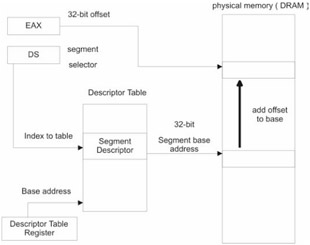
The best way to understand segmentation on Intel is to take a visual look at how it is implemented. A picture is worth 1,024 words, and that is particularly true in this case. So take a good, hard look at Figure 1.9 and compare it to Figure 1.8. You might also want to bookmark Figure 1.9 so that you can return to it when needed.
The first thing to note is that protected mode uses the full-blown set of Pentium registers displayed in Figure 1.2. Back to 32-bit registers we go. Also, the segment registers no longer store 16-bit segment address values. Instead, it holds what is known as a segment selector.
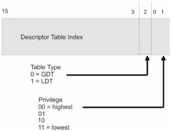
A segment selector is a 16-bit data structure containing three fields. Its composition is displayed in Figure 1.10. The really important field is the index field. The index field stores an index to a descriptor table. Index values start at zero.
| Note |
The index field in the segment selector is not an address. It is an index like the kind of index you would use to access an array element in C. The processor will take the index and internally do the necessary math to match the index to the linear address corresponding to that index. Note that I said linear address, not physical address. For the time being, linear and physical addresses are the same, but when paging is enabled, they are not. Keep this in mind.
|
A descriptor table is an array of entries in which each entry (known as a segment descriptor) describes the attributes of a specific memory segment. Included in a descriptor is the base address of the memory segment that it describes. The 32-bit offset address is added to the segment descriptor's base address in order to specify the address of a byte in memory.
There are two types of descriptor tables: the Global Descriptor Table (GDT) and the Local Descriptor Table (LDT). Every operating system must have a GDT, but having one or more LDT structures is optional. Usually, if an LDT is to be used, it will be utilized to represent the memory segments belonging to a specific process. The base address of the GDT is stored in the GDTR system register. Likewise, the base address of the LDT is stored in the LDTR register. Naturally, there are special system instructions to load these registers (i.e., the LGDT and LLDT instructions).
| Note |
Almost all of the operating systems this book examines focus on the GDT and offer very minimal use of the LDT (if they use it at all).
|
The GDTR is 48 bits in size. One unusual characteristic of the GDTR is that it stores two distinct values. The first 16 bits contain the size limit, in bytes, of the GDT. The next 32 bits store the base linear address of the GDT in physical memory. This is illustrated in Figure 1.11.
|
1.
|
How does the processor map a segment selector's index to a descriptor?
|
|
Answers
|
1.
|
The processor takes the index, specified by the segment selector, multiplies the index by eight (as in 8 bytes because descriptors are 64 bits in length), and then adds this product to the base address specified by GTDR or LDTR.
|
| Note |
In case you are looking at Figure 1.2 and wondering about the other two memory management registers, IDTR and TR, I did not forget them. They are not as crucial to this discussion as GDTR and LDTR. The IDTR and TR registers are used to manage hardware interrupts and multitasking. This book is focused on pure memory management, so I will not discuss these registers in any detail. If you happen to be interested, I recommend that you pick up the Intel manual referenced at the end of this chapter.
|
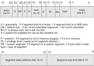
Earlier I mentioned that segment descriptors store the base linear address of the memory segment they describe. However, they also hold a whole lot of other metadata. Figure 1.12 should give you a better idea of what lies within a segment descriptor. In this figure, I have broken the 64-bit descriptor into two 32-bit sections. The higher-order section is on top of the lower-order section.
There is a lot of information packed into those 64 bits. As you can see, several fields are broken up and stored in different parts of the descriptor. There are two fields that might not be obvious just from looking at Figure 1.11. First is the SS flag, which indicates whether the segment is a system segment or just a normal code/data segment. A system segment, in case you are scratching your head, is a segment that is used to provide interrupt handling and multitasking services. I will not investigate either of those subjects.
| Note |
You will see a number of 1 -bit flags in the following few sections. For future reference, a bit is set when it is one. A bit is cleared when it is zero. Low-level operating system code is rife with bit-based manipulation. There is no way around it. Engineers who work with high-level languages tend to look down on engineers who write this type of low-level code. They are called bit-bashers or bit-twiddlers. Programmers can be cruel.
|
Assuming that the SS flag is set, the 4-bit type field in the descriptor describes the specific properties of the segment:
Table 1.1
|
Bit
|
Type
|
Description
|
|
11
|
10
|
9
|
8
|
|
0
|
0
|
0
|
0
|
data
|
read-only
|
|
0
|
0
|
0
|
1
|
data
|
read-only, accessed
|
|
0
|
0
|
1
|
0
|
data
|
read-write
|
|
0
|
0
|
1
|
1
|
data
|
read-write, accessed
|
|
0
|
1
|
0
|
0
|
data
|
read-only, expand down
|
|
0
|
1
|
0
|
1
|
data
|
read-only, expand down, accessed
|
|
0
|
1
|
1
|
0
|
data
|
read-write, expand down
|
|
0
|
1
|
1
|
1
|
data
|
read-write, expand down, accessed
|
|
1
|
0
|
0
|
0
|
code
|
execute-only
|
|
1
|
0
|
0
|
1
|
code
|
execute-only, accessed
|
|
1
|
0
|
1
|
0
|
code
|
execute-read
|
|
1
|
0
|
1
|
1
|
code
|
execute-read, accessed
|
|
1
|
1
|
0
|
0
|
code
|
execute-only, conforming
|
|
1
|
1
|
0
|
1
|
code
|
execute-only, conforming, accessed
|
|
1
|
1
|
1
|
0
|
code
|
execute-read, conforming
|
|
1
|
1
|
1
|
1
|
code
|
execute-read, conforming, accessed
|
Accessed memory segments are segments that have been recently accessed so that bit 8 is set. Expand down segments are useful for creating stacks because they support memory constructs, which grow from high memory down toward low memory. Conforming code segments allows less privileged code segments to jump to them and execute their code at the lower privilege level.
Security-conscious system engineers would be wise to exercise caution with regard to the circumstances in which they allow operating system segments to be conforming.
|
1.
|
OK, so we understand how the segments are referenced and what kind of metadata the segment descriptors store. How are these memory segments protected?
|
|
Answers
|
1.
|
As it turns out, the segment selector and segment descriptor contain most of the information needed to implement a protection scheme. The processor makes ample use of this metadata to track down memory access violations. For example, the limit field in the segment descriptor is used to help keep memory from being referenced beyond the designated last byte of a memory segment. Also, the type field in the segment descriptor ensures that a segment that is specified as read-only is not written to. The privilege fields in the segment selector and segment descriptor are used by the processor to prevent a program from illegally executing code or data that has a higher privilege.
|
| Note |
It is easy to get confused. 0x00 is the highest privilege even though it is the lowest number.
|
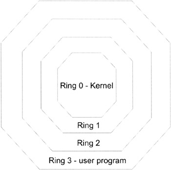
Privilege levels are how the operating system prevents user applications from manipulating the kernel image and compromising security. In the real mode discussion, you saw how easy it was to cause havoc and crash the system. I merely waltzed over to the interrupt vector table and erased it. In protected mode, this threat can be dealt with. Vital data structures and operating system code can be safeguarded at the hardware level.
Intel supports four different privilege levels (0–3). Another way to say this is that Intel supports four rings of protection. These rings are illustrated in Figure 1.13 on the following page. This is actually a pretty simple scheme as far as memory protection is concerned. Decades ago when Control Data was building the NOSVE operating system, the architects wanted to have 15 rings of protection! The odd thing about contemporary operating systems like Linux and Windows is that they only implement two rings of protection (one for the kernel and another for everything else). They don't take full advantage of the facilities offered by the Pentium.
When a memory location is referenced, the processor performs a series of checks. These checks occur at the same time that the memory address is resolved to its physical location. Because these checks are performed concurrently with the address resolution cycle, there is no performance hit. This is the true beauty of pushing memory management down to the hardware.
If one of the processor's various checks discovers a protection violation, the processor will generate an exception. An exception is a signal produced by the processor. Exceptions are caught and processed using a variation of the processor's interrupt handling features. The exact steps taken are beyond the scope of this discussion. In very general terms, the processor will use special data structures, like the Interrupt Descriptor Table (IDT), to hand off exceptions to the operating system, which can then decide what to do. The operating system is actually responsible for establishing and setting up things like the IDT on behalf of the processor when it bootstraps. This allows the operating system the freedom to register special handlers with the IDT so that the appropriate routines can be invoked when a memory violation occurs.
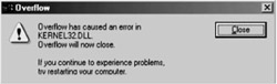
When a memory exception occurs in Windows, a dialog box will typically appear to announce an access violation and Windows will terminate your program. To see what I mean, compile and run the following program under Windows:
There is a blatant array overflow in the code above. When you run this application, it will crash and Windows will present you with a dialog box like the one shown in Figure 1.14. If you've never seen a dialog box like this before, take a good look. If you do any sort of pointer-intensive development on Windows, you are bound to see it sooner or later.
I have not said much about the control registers. The only control register relevant to this current section is the CR0 control register. We'll see a couple of the other control registers in the next section. The CR0 register's first bit (the lowest-order bit) is known as the PE flag (as in Protected Enable). By setting the PE flag to 1, we switch the processor into protected mode and enable all of the segment protection features discussed earlier. Here is a snippet of assembly code that performs this crucial task:
Another equivalent way to do this is to use the special-purpose SMSW and LMSW system instructions:
You've heard a lot of terms bandied about here: selector, descriptor, etc. If this is your first time reading about protected mode, you may still be confused about what is what. Here is a short summary to help you keep all the cast members of this sitcom organized:
If paging has not been enabled, the final address produced by the scheme in Figure 1.9 is also a physical address, which is to say that it is the same 32-bit value that the processor places on its 32 address lines.
If paging is enabled, this is not the case; this leads us to the next section.
Protected Mode Paging
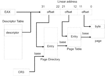
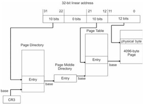
When paging is enabled, the address resolution scheme in Figure 1.9 becomes a bit more complicated. Take a look at Figure 1.15. Take a deep breath, and try not to panic.
Basically, we have taken the address resolution process in Figure 1.9 and appended it with several steps so that we can accommodate all of the extra bookkeeping needed for paging. The address formed by the segment descriptor and the offset address in Figure 1.9 is no longer the address of a byte in physical memory. Instead, a 32-bit quantity is formed that is composed of three distinct offset addresses. Two of these offset addresses are 10 bits in size and the remaining offset address is 12 bits in size.
| Note |
I will refer to this three-part, 32-bit quantity as a linear address to help distinguish it from the physical address of a byte in memory. The GDTR register holds the linear address of the base of the GDT data structure. Now you know why I emphasized this distinction earlier.
Code that runs in protected mode with paging enabled lives in the alternate reality of linear addresses. Such code deals with "fake" 32-bit addresses that seem real enough to the code. Behind the scenes, the processor resolves fake/linear addresses to addresses that specify actual physical storage.
|
| Note |
Paging facilities on the Intel platform were first introduced so that the processor could backfill unused areas of system memory (0xB0000 to 0xFFFFF) with the EMM386.EXE program.
|
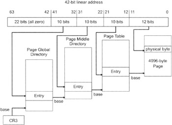
The last 10 bytes of the linear address are an offset address of an entry in the page directory. The page directory is just an array of 32-bit entries whose base address is stored in the CR3 control register. A page directory's entry contains, among other things, the base address of a page table.
Given that a page directory entry has referenced the base address of a certain page table, the middle 10 bytes of the linear address serve as an offset address into that page table. This offset address references a 32-bit page table entry. The 32-bit page table entry contains, among other things, the base address of an actual 4KB page of memory.
This is where the first 12 bytes of the linear address come into play. These 12 bytes form an offset address that is added to the base address in the page table entry. The sum of these values forms an actual physical address of a byte in virtual memory. This byte is either in DRAM or has been paged to disk. You might also notice that a 12-bit offset limits the size of the memory page, in this case, to 4,096 bytes (4KB).
| Note |
The base address stored in the page table entry is 20 bits in size. The processor assumes that these are the 20 most significant bits in a 32-bit base address, which is another way to say that the extra 12 bits are implied and all zero.
This is similar to real mode, where the segment address, expressed in hexadecimal, has a single implied zero at the end. This convention guarantees that the base address of a page always occurs in multiples of 4KB.
|
| Note |
Most operating systems assign each process their own page directory so that each program's linear address space maps to a different section of physical storage. This guarantees, as long as the page structures entries are not the same, that one process will not be able to access the physical memory of another process.
|
If the byte referenced in the page is in physical memory, then we are done. If the byte is not in memory, then a page fault is generated. When this happens, the processor will produce a page fault and hand it off to the local operating system using the exception handling data structures. The operating system is expected to set these data structures up. The operating system, once it has received the fault signal, will then load the page containing this byte into DRAM so that it can be manipulated. Page faults are the backbone of virtual memory on the Intel hardware.
Now you know why your computer's hard drive goes crazy when you have too many applications running. The computer is busy moving programs, or parts of programs, on and off the hard drive. Thrashing occurs when you have so many applications loaded that the computer is too busy managing them and has no time to actually run them.
| Note |
For the sake of simplicity (and sanity) I am going to stick to a 4KB paging scheme that uses only 32 address lines. This is shown in Figure 1.15. Intel has paging schemes where the page size is 4MB or 2MB. However, I don't see much use for a 4MB or 2MB paging scheme. Perhaps these larger paging settings were introduced to help kernels save their own images. There are high-availability operating systems, like EROS, that periodically save an image of the entire operating system. The only thing that would make these two larger paging schemes valuable, in the traditional sense, would be dramatic advances in disk I/O hardware.
|
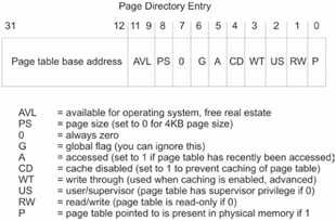
Let's take a closer look at what the page directory and page table entries look like. (See Figure 1.16.)
A page directory entry has a number of special-purpose flags related to caching that I am not going to go into. The really important fields of the entry are the base address of the page table and the page size (PS) flag. The present flag (P) is maintained by the local operating system and is used to indicate if the page table is present in memory. If it is not, the page table will need to be loaded via a page fault so that the address resolution cycle can continue. Most operating systems, however, are wise enough to leave their crucial data structures in memory.
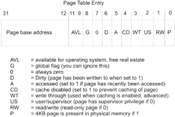
The layout of a page table entry is displayed in Figure 1.17. As you can see, it is very similar to the setup of the page directory entry. The difference is that the fields in a page directory entry are concerned with a page table. The fields in the page table entry are concerned with a 4KB page of memory.
One new thing you might notice is the dirty bit. The dirty bit indicates that the page being referenced has been written to recently. The present (P) flag and the dirty (D) flag are both used by the operating system to help manage the process of paging. The operating system will usually clear the dirty flag when a page is loaded into DRAM for the first time. The processor will then set the dirty bit the first time that the page is updated.
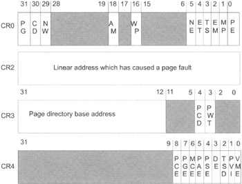
You've already seen how the PE bit in CR0 is used to switch the processor into protected mode. Using the paging facilities of the processor requires even more participation of the control registers. Figure 1.18 displays a summary of important control registers. Reserved areas that should not be modified are shaded gray.
The CR0 is used to control the processor mode and state of the processor. In the last section, we took a look at the PE flag, which is responsible for placing the processor in protected mode. The other really important flag in CR0, as far as paging is concerned, is the PG flag at the other end of the register. When the PG flag is set, the processor is enabled for paging. When the PG flag is cleared, linear addresses are treated like physical addresses.
The CR1 is reserved, which is a nice way to say that it isn't used for anything. This is why I didn't include it in Figure 1.18. For the remainder of this section, you can ignore CR1. My guess is that CR1 may have been created for the sake of some future use.
| Note |
Digging a well before you are thirsty is not a bad idea. Any software architects worth their salt will make accommodations for future modification and extension. If you have ever worked with the Win32 API, you will, no doubt, have noticed a number of ambiguous void* function parameters reserved for future use.
|
The CR2 register is used to store the linear address that has caused a page fault. Mercifully, this value takes up the entire register.
The CR3 plays a central role in the resolution of physical addresses when paging has been enabled. Specifically, this register holds the base address of the page directory. If you look at Figure 1.15, you will see that CR3 plays a vital role in the address resolution process. If CR3 is corrupt, you can kiss your memory manager goodbye. The other two flags (PCD and PWT) in this register are related to caching and are not directly relevant to the immediate discussion.
The CR4 register is used to enable a couple of advanced mechanisms. For example, the PAE flag enables four extra address lines when it is set. This would bring the number of address lines to 36. Note that the PG flag must be set in CR0 in order for PAE to be effective. Another flag of interest is the PSE bit. If PSE is cleared to zero, the page size is 4KB. If PSE is set, the page size is 4MB. If both PAE and PSE are set, the page size is 2MB.
Paging as Protection
Traditionally, paging has been used to artificially expand the amount of memory to which a processor has access. Nevertheless, the Intel architecture has embedded enough functionality into its paging scheme that it is possible to use only paging facilities to implement memory protection. In fact, if you wanted to push the envelope, you could turn off segmentation-based protection and rely completely on paging to provide memory protection. Naturally, this kind of scenario is a little unusual, and there are a few conditions that need to be satisfied.
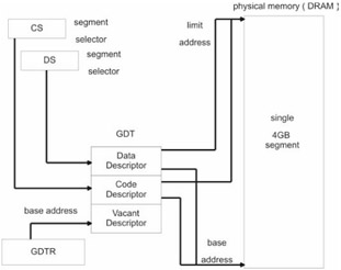
The first condition is that a flat memory model is implemented. In a flat memory model, there is one big segment. It is the simplest possible memory model that can be used in protected mode. Everything shares the same memory segment, and all the protective services provided by segmentation are thrown to the wind. A flat memory model is implemented by creating a GDT with three entries. The first entry to the GDT is never used for some reason, so in a sense it is just a placeholder. The second and third descriptors are used to represent code and data segments. The trick is to have both descriptors point to the same segment. The segment these descriptors point to has base address 0x00000000 and a size limit of 4GB. The size limit is set to the maximum possible value (0xFFFFFFFF) in order to prevent "outside of limit" exceptions from being thrown.
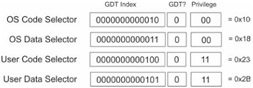
If you use a segment register in an assembly code instruction, like DS, ES, or CS, it must contain a segment selector that indexes one of the two valid descriptors in the GDT. Keep in mind that there are three possible selectors. Two of the three possible segment selectors point to the code and data segment descriptors. There is also a segment selector that points to the vacant segment descriptor, called a null selector. Assuming a privilege of zero is used, these three selectors will look like this:
The flat memory model setup is displayed in Figure 1.19.
| Note |
Don't forget about the first segment descriptor (index = 0) in the GDT being vacant. This is a tricky point, and the Intel docs seem to mention it only in passing.
|
Given that a flat memory model is implemented, none of the traditional segmentation checks can be performed. This leaves us with two ways to protect areas of memory, assuming that paging has been enabled. Both of these paging-based mechanisms rely on the information in page table entries.
If you look back at Figure 1.17, you will see that there is a read-write flag (bit 1) and also a user-supervisor flag (bit 2). The user-supervisor flag can be used to institute a two-ring security scheme. For example, by placing pages that constitute the operating system in supervisor mode and application pages in user mode, the kernel can be protected from malicious programs. If a user application attempts to access pages that are in supervisor mode, the processor will generate a page fault.
The read-write flag can be used to help enforce the user-supervisor division. Specifically, when the processor is executing code in a supervisor page, it can read and write anything. In other words, the read-only flag for other memory pages is ignored. However, if the processor is executing code in a user page, it can only read and write to other user-level pages. If it tries to access a page marked with supervisor status, the processor generates a page fault. A user page's ability to access other user pages depends on the status of their read-write flags, which is to say that user-level code must obey the read/write permissions of all the other pages.
Addresses: Logical, Linear, and Physical
I have made certain distinctions between types of addresses in this chapter. It is easy to get them confused. I am going to try to reinforce this distinction by devoting an entire section to the topic. On Intel hardware, there are three types of addresses:
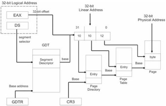
Take a look at Figure 1.20 on the following page, which shows the entire address resolution cycle when both segmentation and paging are used.
A physical address is the address of a byte in DRAM. It is the value that the processor places on its address lines in order to access a value in chip-based memory.
The logical address is the address that is specified by the segment register and the general register. Only in real mode does the logical address correspond to a physical address. This is because real mode doesn't use segmentation or paging and Figure 1.19 does not apply at all. You might also want to keep in mind that the offset portion of a logical address does not necessarily have to be stored in a general register; I am just using a general register for the sake of illustration.
The linear address is the 32-bit value that is formed using the base address value in the segment descriptor and the offset value in the general register. If paging is not being used, the linear address corresponds to an actual physical address.
If paging facilities are being used, the linear address will be decomposed into three parts and the whole page directory/page table cycle will need to be performed in order to arrive at a physical address.
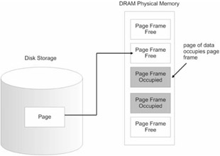
Page Frames and Pages
This is another area where confusion can creep in. I can remember confusing pages and page frames when I first started looking at memory management. A page frame is not the same as a page. When paging is enabled, physical memory (i.e., DRAM) is divided into 4KB units called page frames. This is analogous to a picture frame, which is empty until you place a photograph in it. A page frame specifies a particular plot of real estate in physical memory. A page, on the other hand, is just a chunk of 4,096 bytes that can either reside on disk or be loaded into a page frame in physical memory. If a page of data is stored on disk, and a program attempts to access that page, a page fault is generated. The native operating system is responsible for catching the fault and loading the page into an available page frame. The operating system will also set the present flag (P) in the page's corresponding page table entry.
The relationship between pages and page frames is illustrated in Figure 1.21.
Case Study: Switching to Protected Mode
You've just waded through a mountain of theory. It's time to take a look at protected mode in practice. In this section, I am going to walk you through jumping from real mode to protected mode. To save myself from being labeled a sadist, I am going to stick to pure segmentation without enabling paging.
| Note |
The following program was written in Intel 80x86 assembler. If you are not familiar with Intel assembly code, you should pick up Barry Brey's book, mentioned in the "References" section of this chapter.
|
Switching to protected mode is a dance that has six steps:
-
Build the GDT
-
Disable interrupts
-
Enable the A20 address line
-
Load the GDTR register
-
Set the PE flag in CR0
-
Perform a long jump
Switching to protected mode is perilous enough that you'll want to disable interrupts so that you have the undivided attention of the processor. Otherwise, you'll run the risk that an interrupt will occur and the processor will have to drop everything and service it. While the processor runs the interrupt handler, instructions could be executed that change the state of your machine enough to foil your attempt to switch modes.
| Note |
Disabling interrupts is how many processors implement the atomic operations needed to maintain semaphores. By disabling interrupts, you can halt any extraneous activity (like a task switch), and this is what allows a snippet of code to run "atomically." I must have trudged through seven or eight books on operating systems before I stumbled upon this fact in Tanenbaum's MINIX book.
|
The third step may be foreign, even to those who know Intel assembler — ah yes, the dreaded A20 address line. When the 8086 was released, it had 20 address lines (A0 through A19). This allowed the 8086 to manage a 1MB address space. Any attempt to access memory beyond 1MB would wrap around to address 0. The Pentium normally uses 32 address lines. However, the Pentium starts in real mode at boot time and will try to mimic the 8086 by leaving the A20 address line disabled as the power-on default.
It just so happens that there is a logical AND gate called the A20 gate, which the A20 address line must pass through on its way to the outside world. Just like a bit-wise AND operator in C, an AND gate requires two inputs. The other input is derived from an output pin on the 8042 keyboard controller. Most peripheral attachments to the PC have their own dedicated microcontroller. The 8042 can be programmed via the OUT assembly command so that it sends a 1 to the A20 gate and enables the A20 address line.
| Note |
More than anything else, the A20 line workaround was basically a kludge to allow compatibility between the 8086 and the 80286. Using an available pin on a keyboard controller to address memory issues is not exactly what I would call an elegant solution. It is not exactly a fast solution either. Yikes!
|
Once the GDTR register has been loaded via the LDTR instruction and the PE flag has been set in CR0, a FAR jump must be performed. In Intel assembler, a FAR jump instruction is used to make inter-segment jumps. This causes both the code segment register (CS) and the instruction pointer register (IP) to be loaded with new values. The motivation behind performing a FAR jump is that it serves as a way to load CS with a segment selector.
The tricky part of the FAR jump is that it must be coded in binary. Before we make the jump to protected mode, we are in real mode. That means that the assembler will be treating instructions using the traditional 16-bit interpretations. If we tried to code the 32-bit FAR jump in assembly language, the assembler (which is chugging along in 16-bit mode) would either signal an error or encode the jump instructions incorrectly. Thus, we are left with doing things the hard way.
Here is the assembly source code in all its glory:
You might notice that I intersperse data with code. Given that everything has to lie in a single segment, I really don't have a choice. It is, however, legal to mix data in with your code, as long as the region of memory storing the data is not treated like code and executed. This is a trick they don't always teach you in the books.
I built the previous program as a .COM executable using Microsoft's MASM. The command line to build the binary is:
The /AT option causes the assembler to construct a .COM file (i.e., /AT means assemble with tiny memory model), which is really nothing more than a raw binary. There are no address relocations or fix-ups to be performed. The /Fl option causes a listing file to be generated. Listing files are a handy way to see what binary encoding your assembler generates.
There is a little bit of a catch. Unfortunately, once the switch to protected mode is made, I can't do that much because the processor expects (and wants) 32-bit machine code. Because the assembler that created the program is running in 16-bit mode, I am plain out of luck.
There is a way around this dilemma: The various snippets of operating system bootstrap code that I have read typically load the kernel into memory before the actual switch to protected mode is performed. This allows the FAR jump to transfer processor control to something that the processor can digest once it has switched modes. The kernel is exclusively 32-bit code, so the processor will have no problem following directions.
The side effect of all this is that you'll need two different compilers to write an OS on Intel. You need a 16-bit compiler to create the boot code and a 32-bit compiler to write the operating system proper. This whole process is illustrated in Figure 1.22.
| Note |
Borland still sells a 16-bit DOS compiler with its Turbo C++ suite. Microsoft sells Visual C++ 1.52, which can also generate 16-bit code. There are also a number of freebie compilers on the Internet that create 16-bit executables. I like Dave Dunfield's MICRO-C compiler.
You can also get Microsoft's 16-bit CL.EXE compiler and MASM assembler for free as part of the Windows Device Driver Kit. MASM consists of two files: ML.EXE and ML.ERR. The only downside is that they do not come with documentation.
|
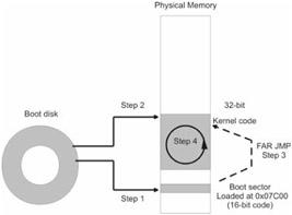
Typically, when a computer is powered on, the BIOS (which is burnt into ROM) will spring into action and look for a bootable device. Remember that PCs start off in real mode. For the sake of simplicity, let us assume that the BIOS locates a bootable diskette in drive A. The BIOS will load the diskette's boot sector into DRAM at address 0000[0]:7C00 (i.e., physical address 0x07C00). This is step number one.
Once the BIOS has loaded the boot sector, it hands over control of the machine to whichever machine instructions now reside at 0000[0]:7C00. However, there are still a number of BIOS services that can be accessed using interrupts. This is where the BIOS plays a crucial role because there is a set of primitive disk I/O interrupts that can be used to load the kernel.
Diskette sectors are 512 bytes in size, so there is really only enough code to load the kernel from disk into memory (step 2) and then switch to protected mode. At the end of the transition to protected mode, the 16-bit boot sector code will perform a manually coded FAR jump to the kernel's entry point (step 3). The kernel code takes matters from there and the system is now in protected mode and executing 32-bit instructions (step 4).
| Note |
You will have to run this program under the auspices of DOS. When I say this, I mean something like DOS 6.22. Do not try to run this program in a virtual DOS console running on Windows 2000. You will also have to make sure that no other memory management software (i.e., HIMEM.SYS, EMM386.EXE) has been installed. Unfortunately, you will need to reboot your machine, seeing as how I overwrite the real mode interrupt vector table that lies at the bottom of memory.
|
If you are interested in taking this discussion to the next level by actually building such a boot sector, I can make a few recommendations. First, you should write the boot sector in assembly code to save space. Next, your boot code should only make use of BIOS interrupts to interact with the hardware. You should not try to invoke a DOS interrupt. DOS will not be there.
Also, you should assemble and link the boot sector program as a 16-bit .COM file binary. PCs boot into real mode and thus only understand the 16-bit instruction set. The boot sector must also be 100% code, which means that you need to avoid extra formatting in the finished executable. This is why you will want to build a .COM file. They are raw binaries.
To place this code on a diskette's boot sector, you will need to use Microsoft's debug utility. The following set of debug commands can be used to perform this task:
The -l command loads the boot.com file into memory. By default, the boot.com file will be loaded by debug to address CS:0x0100. The next command takes the instructions starting at this address and writes them to drive A (i.e., drive 0) starting at logical sector 0. A single, 512-byte sector is written. This may be easier to understand by looking at the general format of the -w command.
Once this has been done, the only thing left to do is to write the kernel and place it on the diskette. You will need a 32-bit compiler to write the kernel, and you should be aware that the compiler will package your kernel code within some executable file format (i.e., the Windows Portable Executable (PE) file format), although I have heard that gcc has a switch that will allow you to build a raw 32-bit binary.
The best way to deal with this extra baggage is to jump over it, which is to say that the boot sector code should take the formatting headers into account and merely sidestep them. You might want to disassemble your kernel file to determine where the header data stops and where your kernel code begins.
You can use debug to write your kernel to the diskette, the same way you as the boot sector.
Closing Thoughts
By now you should understand why memory management requires the operating system and the processor to work closely together. Nevertheless, the roles that the hardware and operating system assume are, without a doubt, complementary.
The processor defines a mechanism for accessing, protecting, and emulating memory. The hardware does, indeed, expect a special set of data structures to be in place, like the GDT and the Page Directory. But these are merely extensions of the mechanism that the processor provides.
It is the responsibility of the operating system to make use of the processor's services and mandate policy for using them. In the next chapter, we will see how different operating systems tackle the issue of implementing memory management policies.
References
Blunden, Bill. "Methodology for OS Construction," Phrack Issue 59. www.phrack.com.
Brey, Barry. Intel Microprocessors 8086/8088, 80186/80188, 80286, 80386, 80486 Pentium, and Pentium Pro Processor, Pentium II, Pentium III, and Pentium IV: Architecture, Programming, and Interfacing. 2002, Prentice Hall, 6th Edition, ISBN: 0130607142. This is a fairly recent book and should take care of any questions you may have. Barry has been writing about Intel chips since the first one came out.
Intel Corporation. Intel Architecture Software Developer's Manual, Volume 3: System Programming Guide. 1997, order number 243192.
MIPS Technologies. MIPS64 Architecture For Programmers, Volume III: The MIPS64 Privileged Resource Architecture. 2001, document number: MD00091.
Podanoffsky, Michael. Dissecting DOS. 1995, Addison-Wesley, ISBN: 020162687X. This book has a useful summary of the boot process on Intel hardware. It also details the design and operation of RxDOS, an enhanced clone of MS-DOS. In the spirit of the original DOS implementation, Podanoffsky has written the entire OS in assembly code. I'm not sure whether to admire his programming fortitude or be disheartened by the lack of portability.
Wahbe,Lucco,Anderson,Graham. Efficient Software-Based Fault Isolation. 1993, Proceedings of the Symposium on Operating System Principles.
Chapter 2: Memory Management Policies
Overview
"If I could remember the names of all these particles, I'd be a botanist."
— Enrico Fermi
In the previous chapter, I discussed the basic mechanisms that processors provide to allow memory regions to be read, modified, isolated, and simulated. Now you are ready to examine the ways in which operating systems construct policies that make use of these mechanisms. The processor presents the means to do things with memory through a series of dedicated data structures, system instructions, and special registers. It offers a set of primitives that can be combined to form a number of different protocols. It is entirely up to the operating system to decide how to use the processor's fundamental constructs, or even to use them at all.
There are dozens of operating systems in production. Each one has its own design goals and its own way of deciding how to use memory resources. In this chapter I will take an in-depth look at the memory subsystems of several kernels, ranging from the simple to the sophisticated. I will scrutinize source code when I can and hopefully give you a better feel for what is going on inside the LeMarchand cube.
In this chapter, I am going to gradually ramp up the level of complexity. I will start with DOS, which is possibly the most straightforward and simple operating system that runs on a PC. DOS is really nothing more than a thin layer of code between you and the hardware. Next, I will kick the difficulty up a notch with MMURTL. MMURTL, unlike DOS, is a 32-bit operating system that runs in protected mode. Finally, this chapter will culminate with a discussion of two production-quality systems: Linux and Windows.
After having looked at all four operating systems, I think that Windows is the most complicated system. Anyone who disagrees with me should compare implementing a loadable kernel module for Linux with writing a kernel mode PnP driver for Windows. There are people who make a living off of telling people how to write Windows kernel mode drivers. Don't get me wrong, the documentation for writing kernel mode drivers is accessible and copious; it is just that the process is so involved. After literally wading through Windows, I gained an appreciation for the relatively straightforward nature of the Linux kernel.
Case Study: Linux
"The memory management on the PowerPC can be used to frighten small children."
— Linus Torvalds
Now we arrive at the production operating systems. Linux has a sophisticated and fairly mature kernel, one that IBM is willing to sell on its mainframes. This additional, but necessary, complexity will make our discussion a little more interesting.
History and MINIX
In the beginning, there was a professor in Amsterdam named Andrew S. Tanenbaum. He wanted his students to be able to get their hands dirty with operating system internals without having to spend months dissecting a large production system. In 1987 Tanenbaum wrote MINIX, a small UNIX clone that originally ran on the 8086/88. He wrote it from scratch and did an impressive job of making its source code easy to read and follow. I can attest to this fact, as I have read portions of the source myself. The code that programs the 8259 PIC is particularly well done. MINIX was also designed as a microkernel-based system so that the file system and memory manager could be switched with new ones at run time.
Tanenbaum received megabytes of e-mail from people who wanted to add features to MINIX. Tanenbaum's goal, however, was to present his students with something that they could explore as a learning tool. Adding extra functionality, like demand paging, was out of the question.
Into the picture came Linus Torvalds, a computer science student in Finland who decided that he was going to hack MINIX into a production-quality operating system. In 1991, Linus made an announcement of his intentions on the MINIX users newsgroup. By December of 1991, version 0.1 was released and Linux began its ascendance to worldwide popularity.
| Note |
It may seem a bit odd, but one of the original detractors of Linux was Tanenbaum! In January of 1992, Tanenbaum left a posting on comp.os.minix titled "Linux is obsolete." Needless to say, he was wrong.
|
Design Goals and Features
According to Linus' first posting on comp.os.minix, Linux started off as "just a hobby." Over the years, it has morphed into a powerful system that easily holds its own against proprietary flavors of UNIX. According to the README file in the kernel's base source code directory, "Linux is a Unix clone written from scratch by Linus Torvalds with assistance from a loosely-knit team of hackers across the Net. It aims towards POSIX compliance."
POSIX, the Portable Operating System Interface, is a specification that establishes a standard set of operating system calls. It was introduced as an effort to help unify the UNIX operating system. Different vendors, like IBM, HP, Sun, and SGI, all sell their own version of UNIX. I should not have to tell you that these vendors have a vested interest in locking customers in to their own special blend. The POSIX standard is an effort to at least give the appearance that there is a least common denominator, even if the different vendors would be more than happy to stab each other in the back.
The POSIX standard is maintained by the IEEE (Institute of Electrical and Electronics Engineers) and is also known as IEEE 1003.1-2001. The full title is:
The last time I looked, the price of this standard was around $176. This is why a search for "POSIX" on Google or Yahoo will not prove very fruitful. Trust me on this. Fortunately, someone in the Linux development effort bought a copy. It was a good investment. Any operating system worth its salt will be POSIX compliant.
The following sample list of features supported by Linux reads like a Christmas list to Santa:
-
Multiuser
-
Symmetric multiprocessing (SMP)
-
Protected mode memory protection
-
Demand-paged virtual memory
-
Dynamically and statically linked libraries
-
Multiple file system support
-
Loadable kernel modules (LKMs)
-
High-performance TCP/IP stack
If you compare this feature list to MMURTL's, you will see why I discussed MMURTL first.
| Note |
It would be very easy to fill an entire book with an explanation of the inner workings of Linux. In fact, I reference a couple of such books at the end of this chapter. I am going to stick to somewhat of a tourist's view in the following discussion; this will allow me to highlight the principal architectural features, which illustrate various memory management policies, without getting too weighed down.
|
Linux and Segmentation
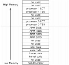
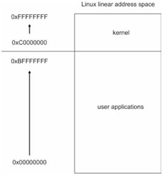
Like MMURTL, Linux makes only minimal use of the Pentium's segmentation facilities. I must say, I was a little surprised by this. I was expecting Linux to implement a full-blown, four-ring segmentation scheme. The Linux kernel does not make use of an LDT. The GDT, which the kernel does use, is fairly small:
These structures are defined in /usr/src/linux/arch/i386/kernel/head.S. The previous assembly code does not use MASM-compatible directives. Instead, it follows AT&T syntax. Linux only uses one more kernel segment than MMURTL, and it is used to accommodate kernel data. Let's dissect the GDT and place the results in a table for easy reading (see Table 2.2).
Table 2.2
| |
Kernel Code
|
Kernel Data
|
User Code
|
User Data
|
|
Base address
|
0x0
|
0x0
|
0x0
|
0x0
|
|
Size limit
|
0xFFFFF
|
0xFFFFF
|
0xFFFFF
|
0xFFFFF
|
|
Limit units
|
4KB units
|
4KB units
|
4KB units
|
4KB units
|
|
32-bit code/data
|
Yes
|
Yes
|
Yes
|
Yes
|
|
Present in memory
|
Yes
|
Yes
|
Yes
|
Yes
|
|
Privilege
|
0x0
|
0x0
|
0x3
|
0x3
|
|
Type
|
Execute/Read
|
Read/Write
|
Execute/Read
|
Read/Write
|
The segment selectors corresponding to these descriptors are displayed in Figure 2.7.
There are 12 descriptors defined in the source code snippet. Four are not used and four are dedicated to advanced power management (APM). The GDT, however, is not guaranteed to be a fixed size. As of kernel version 2.4, every CPU on the motherboard gets two segment descriptors in the GDT. Each CPU gets a descriptor specifying a Task State Segment (TSS) and a descriptor specifying a segment that stores a Local Descriptor Table (LDT). This is illustrated in Figure 2.8.
Notice how each processor's TSS and LDT segment descriptor is delimited by two unused segment descriptors.
The segment descriptor pointing to an LDT in Linux typically stores the address of the default_ldt variable. The default_ldt variable is basically an LDT with a single NULL descriptor. It is declared in /usr/src/linux/include/asm-i386/desc.h.
The default_ldt variable is defined in /usr/src/linux/ arch/i386/kernel/traps.c.
The reason that Linux can get away with its minimal GDT is that all processes use the same linear address space but are stored in different regions of physical memory. This is very similar in spirit to MMURTL's memory management approach.
Notice the privilege difference between the kernel segments and the user segments. Unlike MMURTL, which gave every segment a privilege of zero, Linux institutes two rings of protection. The kernel executes with privilege level 0x0, and user code executes with privilege level 0x3.
Linux and Paging
The techniques of segmentation and paging are both used to divide up an address space into distinct regions. So in a way, perhaps the lack of an elaborate segmentation scheme in Linux is merely an effort to avoid being redundant. To implement demand paging and protection, Linux uses Intel's paging facilities.
Three-Level Paging
In the previous chapter, I examined what is known as a two-level paging model that uses two bookkeeping data structures: page directories and page tables. Linux adds another data structure and extends the linear address that it uses so that it has a three-level paging model. I assume that this has been implemented to allow Linux to seamlessly extend itself to 64-bit architectures. The three-level paging model is displayed in Figure 2.9
The CR3 control register holds the base address of the page global directory. The highest-order 10-bit section of the linear address stores an offset address into the page global directory and is added to the base address in CR3 to specify a page global directory entry. This entry stores the base address to a page middle directory structure.
The middle 10-bit section of the linear address is added to the base address in the global page directory entry to specify an entry in the page middle directory. The entry in the page middle directory stores the base address of a page table.
The lowest-order 10-bit portion of the linear address is added to the base address in the page middle directory to specify an entry in the page table. This page table entry will specify the base address of a physical 4KB page of memory. The 12-bit portion of the linear address is an offset into the physical page and specifies an actual physical byte of memory.
|
1.
|
Wait! Hold on a minute! (At least, I hope this is what you are thinking.) The Pentium is a 32-bit processor that deals with 32-bit linear addresses. How does Linux resolve this fact?
|
|
Answers
|
1.
|
As it turns out, Linux assumes that the portion of the linear address that serves as an offset into the page middle directory consists of zero bits. However, the page middle directory is kept in the address resolution cycle for the sake of forward compatibility. It is just that Linux fixes the page middle directory so that it has a single entry. In the case of the 32-bit Pentium, the page global directory reverts to the page directory we know from earlier. These adjustments are illustrated in Figure 2.10.
To get a ground-zero look at how the engineers saw their own solution, here is how the Linux source documentation explains the workaround in /usr/src/linux/include/asm-i386/pgtable.h:
|
| Note |
When Linux runs on a 64-bit processor, the 42-bit linear address in the three-level model will represent the 42 least significant bits in a 64-bit linear address. The other, higher-order bits would be assumed to be zero.
|
Linux uses a number of C structures to represent table entries. The page directory and the page table themselves are just arrays of these 32-bit entries. These structures are defined in /usr/src/linux/include/asm-i386/page.h.
These structures will change for special cases, like when the address bus has been extended to 36 bits or when a 64-bit processor is being used. I am sticking to the run-of-the-mill 32-bit Pentium scenario for the sake of simplicity.
Remember from the previous chapter that it is the duty of the operating system to maintain the state of the present flag (P) in the page table. It is also the duty of the operating system to clear the dirty bit (D) when a page is loaded into memory. The processor will set the dirty bit the first time that the page is accessed. This entails accounting work on the part of the operating system. To this end, Linux uses a set of macros to perform its accounting. For example, the following macros are used to query the P flag in the page table entry, set the page table entry, and clear the page table entry:
There are a multitude of other such flags in /usr/src/linux/include/asm-i386/pgtable.h. As with many portions of the Linux code base, these macros take different forms when the kernel is not running on a 32-bit Pentium.
There is also a significant amount of page metadata that is external to Intel's native paging data structures, which is to say that the metadata is relevant to Linux without being mandated by the processor. For example, Linux allows pages to be locked. A locked page of memory cannot be written out to disk. Kernel pages are locked. The kernel also keeps a record of how many processes are using a particular page of memory. These extra features are supported by the page structure:
This structure is defined in /usr/src/linux/include/linux/mm.h. The count member keeps track of how many processes are using a page. The count variable is zero if the page is free. The flags member stores 32 Boolean fields. Its first bit, the PG_locked field, is used to indicate if a page is locked.
The macros above are also defined in /usr/src/linux/include/linux/mm.h.
Page Fault Handling
Page faults are the core mechanism that allow Linux to support memory protection and demand paging. The page fault handler in Linux is a function called do_page_fault() defined in /usr/src/linux/arch/i386/mm/fault.c:
The regs argument is a pointer to a structure containing the contents of the registers when the page fault was generated.
The error_code argument wraps a 3-bit value that was generated as a result of the page fault. It is this little 3-bit value that is absolutely crucial. It will determine what the kernel will do. If a memory access violation has occurred, the kernel will probably kill the process that made the illegal memory access. Sometimes this means putting the kibosh on the kernel! Linux uses the Supervisor/User flag in page table entries to implement the distinction between kernel code and user code.
If a process has attempted to access a page that is on disk (i.e., its present (P) flag is cleared), the kernel will need to take care of loading the page into memory. This is one feature that definitely separates Linux from MMURTL. MMURTL only uses paging as a way to divide up and manage memory. Linux takes things a step further and allows pages to be swapped to disk storage. Naturally, this requires a whole load of additional instructions and logic, making Linux a far more intricate operating system.
Table 2.3 explains the format of the 3-bit value passed to do_page_fault and the information that it stores.
Table 2.3
|
Bit
|
Value
|
Meaning
|
|
0
|
0
|
Page fault caused by accessing a page that has its present (P) flag cleared
|
|
0
|
1
|
Page fault caused by invalid access right
|
|
1
|
0
|
Page fault caused by access of type execute or type read
|
|
1
|
1
|
Page fault caused by access of type write
|
|
2
|
0
|
Page fault occurred while the processor was in kernel mode
|
|
2
|
1
|
Page fault occurred while the processor was in user mode
|
Memory Allocation
When Linux boots, the kernel reserves a region of physical memory to store its code and data structures. The pages of memory that constitute this region are locked and cannot be written to disk. The kernel is loaded into physical memory starting at physical address 0x00100000 (i.e., just above 1MB). This is done to avoid overwriting BIOS code at the bottom of memory and VRAM that lies within the first megabyte. The size of the kernel's image in memory is a function of the features that were built into it when it was compiled, so it is not really feasible to give a definite upper boundary to the kernel's region in physical memory. The remaining part of physical memory (not reserved by the kernel, BIOS, or VRAM) is known as dynamic memory. Figure 2.11 displays this basic organization of physical memory.
The linear address space is an alternate reality that is created by the kernel and the processor (the programs happen to think it is real). It has little or nothing in common with the actual arrangement of code and data in physical memory. The linear address space of Linux is broken into two basic regions. The linear address range from 0 to PAGE_OFFSET-1 is used for user programs. The linear address range from PAGE_OFFSET to 0xFFFFFFFF (4GB) is reserved for the kernel. The PAGE_OFFSET macro is defined in /usr/src/linux/include/asm-i386/page.h as 0xC0000000. This means that the kernel uses the last gigabyte of linear memory, and the user applications reside in the first three gigabytes. The layout of the Linux linear address space is displayed in Figure 2.12.
| Note |
A gigabyte of linear address space does not necessarily translate into a gigabyte of physical memory. For example, if the kernel consumes 4MB of physical memory, only 4MB of linear address space will be active in the operating system's gigabyte of linear memory.
|
The kernel can allocate dynamic memory for itself by invoking one of three functions:
The __get_free_pages () function is defined in /usr/src/linux/mm/page_alloc.c. It uses the buddy system algorithm to allocate 2order pages of contiguous memory. The gfp_mask dictates how the free pages will be looked for. For example, if gfp_mask is set to __GFP_HIGH, the priority of the memory request is set to the highest level. There are a whole set of gfp_mask values in /usr/src/linux/include/linux/mm.h.
The kmalloc() function is defined in /usr/src/linux/mm/slab.c and allocates size number of bytes. Instead of a buddy system algorithm, it uses an approach similar to the slab allocator designed by Sun Microsystems in 1994. The kmalloc() function manages 4KB pages internally so that smaller amounts of memory can be requested.
The vmalloc () function is defined in /usr/src/linux/include/linux/vmalloc.h. This function allows noncontiguous pages of memory to be allocated. The two previous functions deal only with contiguous regions of memory. The size argument indicates the number of pages to allocate.
The kernel allocates dynamic memory for user applications when the sys_fork() system call is made. The sys_fork() function causes a process address space to be requisitioned from memory for the user program. A process address space consists of a set of memory regions in the computer's linear address space. Each region is a contiguous set of linear addresses and is assigned a set of access rights. The size of each memory region is a multiple of 4KB.
Linux user applications traditionally have four memory regions. One is used to store the application's machine code, one is used to store the application's data, another serves as a stack, and the fourth region is used as a heap to provide space for run-time storage requests. The arrangement of these regions in the linear address space is a function of the development tools that were used to build the application and operating system's program loader. For example, Figure 2.13 displays two different ways to organize memory regions.
The sys_fork() function in /usr/src/linux/arch/i386/kernel/process.c is just a wrapper for do_fork(),which takes care of the real work. The do_fork() function calls a function named copy_mm() to take care of creating the new task's address space. The copy_mm() function, in turn, calls a function named mm_init(), which eventually ends up in a call to ___get_free_pages().
This string of function calls creates a memory descriptor for the new process and populates it. A memory descriptor, in terms of the C programming language, is just a mm_struct structure in the file /usr/src/linux/include/linux/sched.h.
The vm_area_struct structure describes a given memory region. Because a process address space usually consists of several memory regions, the mm_struct process address space descriptor will need to keep a list of vm_area_struct variables. This is what the mmap member variable is for.
The pgd member variable points to the page global directory allocated to a process address space. Each process in Linux owns a single page global directory, and this points to one or more page tables. Each process also has its own CR3 value. This register's contents are saved in the task's TSS when its corresponding task is suspended.
The total_vm member specifies how many pages have been allotted for a process, and the locked_vm field determines how many of these pages are locked. The rss member variable indicates the number of page frames in RAM that the process is actually using.
There are a number of fields, like start_code and end_code, that store the initial and final linear addresses of each memory region. The location of command line arguments on the task's run-time stack is specified by the arg_start and arg_end member variables.
Memory Usage
For a system-wide summary of memory usage, use the free command:
Mem and swap are simply physical memory and disk swap space. Linux tends to keep things simple, and this is part of its appeal to me. The data displayed by free is actually an abbreviated version of what you would get by looking in the kernel's /proc directory:
If you are interested in looking at the memory usage of a particular process, the ps command can be applied:
This command pumps out the size in bytes of physical memory used, the size in bytes of linear address space being used, percent of memory used, and the process ID of the init command. If you need to determine which tasks are running on a Linux machine in order to use the ps command that I just showed you, I would recommend using pstree. The pstree command displays an ASCII tree of all the tasks currently running.
Example: Siege Warfare
In the Middle Ages, siege warfare was a common form of battle. A siege would occur when a larger army surrounded a smaller army that was holed up inside a stronghold. The besiegers had two basic options: storm the fortifications or wait the enemy out. Both options could be expensive. War has always been, and still is, founded on financial concerns. Storming the stronghold could be costly in terms of lives. Starving an enemy into submission was also expensive because it cost a significant amount of money to sustain a standing army in terms of food and supplies. Although movies may favor the storming tactic, some of the more spectacular victories were obtained through patience.
"So, you think you could out-clever us French folk with your silly knees-bent running about advancing behavior?"
— French guard, Monty Python and the Holy Grail
Because Linux has a two-ring privilege scheme, the innards of the operating system are not exposed and vulnerable like they are in DOS. We cannot simply rip out entries in the interrupt vector table or write messages to the screen by modifying VRAM. We are back in elementary school: To do anything, we need permission. The kernel policies, in conjunction with Intel hardware, have built fortifications against malicious programs. The crown jewels, operating system data structures, have been hidden far behind thick, formidable walls.
In this example, I will lay siege to Linux in an attempt to demonstrate its memory protection facilities. As in the Middle Ages, I can either storm the walls or wait it out. I suspect that waiting it out and starving the kernel of resources is still the most effective way to bring a computer to its knees. An example of this kind of attack would be a memory leak.
I ran the following program on Linux:
The machine I tested this code on had 64MB of DRAM. At about 110MB of allocated virtual memory, my computer's paging subsystem began to thrash. A few moments later, I lost control of my machine; I couldn't even gain the attention of a terminal console to kill the process. I literally had to unplug my computer. A more insidious version of this program would sleep at odd intervals and only allocate small bits of memory. This kind of attack tends to creep up on systems that aren't being monitored carefully.
Next, I tried the more audacious approach of directly assaulting the kernel:
Here is the console output that I received:
"You silly King..." As you can see, the Linux kernel has been heavily fortified against such brazen direct attacks. It noticed my attempt for access to the kernel's memory image and sent me to /dev/null. Trying this type of straightforward tactic is about as wise as starting a land war in Asia. Inconceivable.
| Note |
However, there is an option that I haven't mentioned. The goal of storming a stronghold is to get inside. There are other, less obtrusive ways of getting past a heavy stone barrier. At the end of the day, nothing beats a generous plateful of treachery. Why spend man-hours of effort to break down a wall when you can sneak by it?
|
Linux Loadable Kernel Modules (LKMs) present the besieging army with an opportunity to dress up like opposing troops and simply walk blithely through the main gate. LKMs are basically software components that can be dynamically added to the kernel image, which is loaded in memory, at run time. An LKM becomes a part of the executing kernel. Why spend all that effort trying to pass a fortification when you can start on the other side to begin with?
| Note |
Once an LKM has been merged with the kernel's image, the LKM's code is a DOS-like situation where the operating system is naked. In this state, we can write to any device files we want. This includes /dev/kmem, the kernel's coveted memory image. We can also modify the /proc file system or perhaps hook an internal kernel function. The potential number of uses is almost infinite. Ba ha ha ha ha (evil laugh).
|
An LKM is really just an ELF object file that is dynamically linked with the kernel. You can create an LKM simply by compiling with the -c option that prevents the linker from being invoked. For example, if you have an LKM source file named 1 km. c, you can compile it into an object file with:
| Note |
The Executable and Linkable Format (ELF) was originally designed by the UNIX System Laboratories (USL) before it was bought by Novell. The ELF specification was a part of the Application Binary Interface (ABI) effort. ELF is a binary format like COFF or Microsoft's PE format. In 1995, the Tool Interface Standard (TIS) group came out with version 1.2 of the ELF specification.
|
LKMs can be loaded/inserted into the kernel at run time with the following command:
The insmod program invokes the sys_init_module () system call, which the kernel uses to register the LKM. If you look at this system call in /usr/src/linux/kernel/module . c, you will see that it invokes a similarly named function in the LKM — init_module(). Try not to get confused by all the various init_module() functions.
To verify that the module is loaded, you can issue the lsmod command:
Equivalent results can be obtained via:
This will provide you with a list of currently loaded modules. Naturally, some modules can be written so that they modify the kernel and are not listed (just a thought). Ba ha ha ha (Neumann laugh).
To remove an LKM from the kernel's image, you can use the rmmod command:
Note how I did not include the . o suffix as I did with insmod. The rmmod command will cause the LKM's cleanup_module () function to be invoked. You should use this as an opportunity to restore the system to its previous state.
| Note |
The init_module () and cleanup_module () are the only functions that are required in order for an object file to serve as an LKM.
|
In the following code, I use an LKM to intercept the sys_chdir system call. This is reminiscent of the DOS example where I stole the keyboard interrupt. I basically take my own version of sys_chdir and use it to wrap a call to the actual system call. This allows me to piggyback the system call code with my own instructions.
The key to system call swapping is the sys_call_table array, which is an array of pointers to system call functions in the kernel. It is analogous to the real mode interrupt vector table. We can change which address gets jumped to for a given system call by switching an entry in the sys_call_table pointer array. In my example code, I make sure to save the old function address so that I can restore the sys_call_table when I am done.
Example: Siege Warfare, More Treachery
We have waged a lengthy siege against Linux and have tried a number of tactics to defeat memory protection. Of the three approaches that I have presented, starving the enemy into submission is the path of least resistance. Then again, you never really get inside the castle walls (i.e., the kernel) with the wait-them-out tactic; you merely get to watch your quarry inside the castle spasm in their death throes. Memory leaks provide only a hollow victory in that they don't allow you to get past the protective walls of the operating system.
Brute force attacks are glaringly fruitless, seeing as how the Pentium and Linux were explicitly designed to protect against such overt methods. Trying to barge into the kernel's linear address space is akin to banging your head against an anvil — the anvil wins every time.
LKMs are a cunning solution, but you need to have root privileges to execute programs such as insmod (ah ha! there's a catch!). Most people who obtain root don't need LKMs once they achieve that vaunted status anyway.
An ingenious and more sophisticated approach is needed.
One of the most devious tactics that I can think of is the buffer overflow attack. In the medieval days, a buffer overflow attack would be implemented by poisoning the besieged army's supply of food and water. They would consume the bad provisions and start acting confused and irrational.
Buffer overflow techniques were made famous by Aleph One's article in issue 49 of Phrack magazine. They rely on a function that uses a call like strcpy() to copy an argument to a local buffer. If a large enough argument is fed to the function, you can overflow the local buffer so that the function's activation record is corrupted. This allows skillful attackers to place their own return addresses and executable code on the activation record and literally hijack the processor's path of execution.
Here is a fairly simple example:
When this program is run, the following output is streamed to the console:
The key of this technique lies in the activation record of the function to which you are feeding arguments. Figure 2.14 displays the normal activation record of the overflow() function.
When the overflow() function is called from main(), the code in main() will pop the address of the string argument on to the stack and call overflow(). This will cause EIP to be indirectly placed on the stack also.
Once execution has jumped to overflow (), the EBP register will be popped on the stack so that it can be used as a frame of reference for the activation record. In addition, space will be allocated on the stack for the buffer[4] local array.
This leaves us with the 16-byte activation record in Figure 2.14. To alter the return address, we merely feed overflow() an argument that is 12 bytes in size. The strcpy() function does the rest by placing 12 bytes in memory starting at the storage allocated for buffer.
The best way to understand this is visually. The before and after strcpy () snapshots of the overflow () stack are displayed in Figure 2.15. Notice how the original return address bytes (retla, … , ret1d) are replaced with four new bytes (ret2a, …, ret2d).
Imagine what would happen if the function to which we passed the oversized argument was in the kernel? You could jump to another function in the kernel. You can augment this technique by placing extra executable code on the stack and having execution jump to that code. This would allow you to execute any code of your choosing and have it execute in kernel mode. Performing a successful buffer overflow attack can give you ownership of a machine. Ba ha ha ha ...
Do not lament. There is hope for those soldiers who are defending the walls of a besieged castle. Buffer overflow attacks can be foiled by replacing strcpy() with strncpy(). The general idea is to replace copying functions with functions that impose a specific boundary. This is more a matter of discipline and code audits than anything else. The people at OpenBSD know this more than anyone else (www.openbsd.com). Commercial vendors like Microsoft are so busy churning out new versions that they cannot invest the time needed to protect against these types of attacks.
In the Middle Ages, defenders of a fortress could rain arrows and boiling oil down on attackers. These defenses were very effective, seeing as how the aggressors typically had nowhere to hide. Having thick walls didn't hurt either. Likewise, Linux sysops can do a number of things to harden their production systems and make attacking them much more expensive:
Table 2.4 provides only a small sample of possible measures. If any of the items that I mentioned are foreign to you, then you will need to do a little homework. For an extended treatment of security on Linux, I recommend a couple of books in the reference section. Some exploits, like buffer overflows, are hard to prevent if you don't have access to source code. This is why you will probably want to visit www.securityfocus.com and get on their bugtraq mailing list. This gives you a way to hear about problems as they are reported.
Table 2.4
|
Measure
|
Benefit
|
|
Shut down unnecessary services
|
Decrease number of potential targets
|
|
Install an intrusion detection system
|
Detect Trojan horses and compromised binaries
|
|
Implement a VPN
|
Foil sniffers
|
|
Disable all dial-up servers
|
Remove the easy path around your firewall
|
|
Place public servers in a demilitarized zone
|
Limit damage done if public boxes are hacked
|
|
Disable zone transfers on DNS servers
|
Prevent information leakage
|
|
Implement password changes/checking
|
Prevent usage of weak and old passwords
|
|
Log data with a dedicated syslog machine
|
Save forensic evidence in the event of an attack
|
|
Enable port scan detection software
|
Preempt an attack before it happens
|
|
Disable NFS and sendmail
|
Use SSH and qmail
|
|
Establish phone call protocols
|
Reduce the risk of social engineering attacks
|
|
Install a dedicated firewall (i.e., CheckPoint)
|
Limit/monitor network traffic to the outside
|
|
|

 LINUX
LINUX 
 Books
Books