Устройства
Two kinds of device files exist: block device files and character device files. Block devices transfer data in chunks, and character devices (as the name implies) transfer data one character at a time. A third device type, the network device, is a special case that exhibits attributes of both block and character devices. However, network devices are not represented by files.
The old method of assigned numbers for devices where the major number usually referred to a device driver or controller, and the minor number was a particular device within that controller, is giving way to a new dynamic method called devfs. The history behind this change is that the major and minor numbers are both 8-bit values; this allows for little more than 200 statically allocated major devices for the entire planate. (Block and character devices each have their own list of 256 entries.) You can find the official listing of the allocated major and minor device numbers in /Documentation/devices.txt.
The Linux Device Filesystem (devfs) has been in the kernel since version 2.3.46. devfs is not included by default in the 2.6.7 kernel build, but it can be enabled by setting CONFIG_DEVFS_FS=Y in the configuration file. With devfs, a module can register a device by name rather than a major/minor number pair. For compatibility, devfs allows the use of old major/minor numbers or generates a unique 16-bit device number on any given system.
5.2.1. Block Device Overview
As previously mentioned, the Linux operating system sees all devices as files. Any given element in a block device can be randomly referenced. A good example of a block device is the disk drive. The filesystem name for the first IDE disk is /dev/hda. The associated major number of /dev/hda is 3, and the minor number is 0. The disk drive itself usually has a controller and is electro-mechanical by nature (that is, it has moving parts). The "
General System File" section in Chapter 6, "Filesystems," discusses the basic construction of a hard disk.
5.2.1.1. Generic Block Device Layer
The device driver registers itself at driver initialization time. This adds the driver to the kernel's driver table, mapping the device number to the block_device_operations structure. The block_device_operations structure contains the functions for starting and stopping a given block device in the system:
 -------------------------------------------------------------------------
 include/linux/fs.h
 760  struct block_device_operations {
 761   int (*open) (struct inode *, struct file *);
 762   int (*release) (struct inode *, struct file *);
 763   int (*ioctl) (struct inode *, struct file *, unsigned, unsigned long);
 764   int (*media_changed) (struct gendisk *);
 765   int (*revalidate_disk) (struct gendisk *);
 766   struct module *owner;
 767  };
 -------------------------------------------------------------------------
The interfaces to the block device are similar to other devices. The functions open() (on line 761) and release() (on line 762) are synchronous (that is, they run to completion when called). The most important functions, read() and write(), are implemented differently with block devices because of their mechanical nature. Consider accessing a block of data from a disk drive. The amount of time it takes to position the head on the proper track and for the disk to rotate to the desired block can take a long time, from the processor's point of view. This latency is the driving force for the implementation of the system request queue. When the filesystem requests a block (or more) of data, and it is not in the local page cache, it places the request on a request queue and passes this queue on to the generic block device layer. The generic block device layer then determines the most efficient way to mechanically retrieve (or store) the information, and passes this on to the hard disk driver.
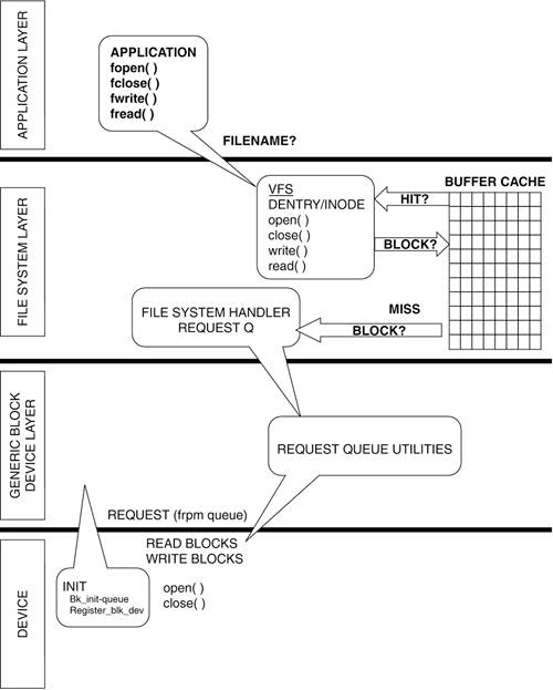
Most importantly, at initialization time, the block device driver registers a request queue handler with the kernel (specifically with the block device manager) to facilitate the read/write operations for the block device. The generic block device layer acts as an interface between the filesystem and the register level interface of the device and allows for per-queue tuning of the read and write queues to make better use of the new and smarter devices available. This is accomplished through the tagged command queuing helper utilities. For example, if a device on a given queue supports command queuing, read and write operations can be optimized to exploit the underlying hardware by reordering requests. An example of per-queue tuning in this case would be the ability to set how many requests are allowed to be pending. See Figure 5.4 for an illustration of how the application layer, the filesystem layer, the generic block device layer, and the device driver interrelate. The file biodoc.txt under /Documentation/block> has more helpful information on this layer and information regarding changes from earlier kernels.
5.2.2. Request Queues and Scheduling I/O
When a read or write request traverses the layers from VFS, through the filesystem drivers and page cache, it eventually ends up entering the block device driver to perform the actual I/O on the device that holds the data requested.
As previously mentioned, the block device driver creates and initializes a request queue upon initialization. This initialization also determines the I/O scheduling algorithm to use when a read or write is attempted on the block device. The I/O scheduling algorithm is also known as the elevator algorithm.
The default I/O scheduling algorithm is determined by the kernel at boot time with the default being the anticipatory I/O scheduler. By setting the kernel parameter elevator to the following values, you can change the type of I/O scheduler:
deadline.
For the deadline I/O scheduler
noop.
For the no-operation I/O scheduler
as.
For the anticipatory I/O scheduler
As of this writing, a patch exists that makes the I/O schedulers fully modular. Using modprobe, the user can load the modules and switch between them on the fly. With this patch, at least one scheduler must be compiled into the kernel to begin with.
Before we can describe how these I/O schedulers work, we need to touch on the basics of request queues.
Block devices use request queues to order the many block I/O requests the devices are given. Certain block devices, such as a RAM disk, might have little need for ordering requests because the I/O requests to the device have little overhead. Other block devices, like hard drives, need to order requests because there is a great overhead in reading and writing. As previously mentioned, the head of the hard drive has to move from track to track, and each movement is agonizingly slow from the CPU's perspective.
Request queues solve this problem by attempting to order block I/O read and write requests in a manner that optimizes throughput but does not indefinitely postpone requests. A common and useful analogy of I/O scheduling is to look at how elevators work. If you were to order the stops an elevator took by the order of the requests, you would have the elevator moving inefficiently from floor to floor; it could go from the penthouse to the ground floor without ever stopping for anyone in between. By responding to requests that occur while the elevator travels in the same direction, it increases the elevator's efficiency and the riders' happiness. Similarly, I/O requests to a hard disk should be grouped together to avoid the high overhead of repeatedly moving the disk head back and forth. All the I/O schedulers mentioned (no-op, deadline, and anticipatory) implement this basic elevator functionality. The following sections look at these elevators in more detail.
5.2.2.1. No-Op I/O Scheduler
The no-op I/O scheduler takes a request and scans through its queue to determine if it can be merged with an existing request. This occurs if the new request is close to an existing request. If the new request is for I/O blocks before an existing request, it is merged on the front of the existing request. If the new request is for I/O blocks after an existing request, it is merged on the back of the existing request. In normal I/O, we read the beginning of a file before the end, and thus, most requests are merged onto the back of existing requests.
If the no-op I/O scheduler finds that the new request cannot be merged into the existing request because it is not near enough, the scheduler looks for a place within the queue between existing requests. If the new request calls for I/O to sectors between existing requests it is inserted into the queue at the determined position. If there are no places the request can be inserted, it is placed on the tail of the request queue.
5.2.2.2. Deadline I/O Scheduler
The no-op I/O scheduler suffers from a major problem; with enough close requests, new requests are never handled. Many new requests that are close to existing ones would be either merged or inserted between existing elements, and new requests would pile up at the tail of the request queue. The deadline scheduler attempts to solve this problem by assigning each request an expiration time and uses two additional queues to manage time efficiency as well as a queue similar to the no-op algorithm to model disk efficiency.
When an application makes a read request, it typically waits until that request is fulfilled before continuing. Write requests, on the other hand, will not normally cause an application to wait; the write can execute in the background while the application continues on to other tasks. The deadline I/O scheduler uses this information to favor read requests over write requests. A read queue and write queue are kept in addition to the queue sorted by a request's sector proximity. In the read and write queue, requests are ordered by time (FIFO).
When a new request comes in, it is placed on the sorted queue as in the no-op scheduler. The request is also placed on either the read queue or write queue depending on its I/O request. When the deadline I/O scheduler handles a request, it first checks the head of the read queue to see if that request has expired. If that requests expiration time has been reached, it is immediately handled. Similarly, if no read request has expired, the scheduler checks the write queue to see if the request at its head has expired; if so, it is immediately handled. The standard queue is checked only when no reads or writes have expired and requests are handled in nearly the same way as the no-op algorithm.
Read requests also expire faster than write requests:  a second versus 5 seconds in the default case. This expiration difference and the preference of handling read requests over write requests can lead to write requests being starved by numerous read requests. As such, a parameter tells the deadline I/O scheduler the maximum number of times reads can starve a write; the default is 2, but because sequential requests can be treated as a single request, 32 sequential read requests could pass before a write request is considered starved. a second versus 5 seconds in the default case. This expiration difference and the preference of handling read requests over write requests can lead to write requests being starved by numerous read requests. As such, a parameter tells the deadline I/O scheduler the maximum number of times reads can starve a write; the default is 2, but because sequential requests can be treated as a single request, 32 sequential read requests could pass before a write request is considered starved.
5.2.2.3. Anticipatory I/O Scheduling
One of the problems with the deadline I/O scheduling algorithm occurs during intensive write operations. Because of the emphasis on maximizing read efficiency, a write request can be preempted by a read, have the disk head seek to new location, and then return to the write request and have the disk head seek back to its original location. Anticipatory I/O scheduling attempts to anticipate what the next operation is and aims to improve I/O throughput in doing so.
Structurally, the anticipatory I/O scheduler is similar to the deadline I/O scheduler. There exist a read and write queue each ordered by time (FIFO) and a default queue that is ordered by sector proximity. The main difference is that after a read request, the scheduler does not immediately proceed to handling other requests. It does nothing for 6 milliseconds in anticipation of an additional read. If another read request does occur to an adjacent area, it is immediately handled. After the anticipation period, the scheduler returns to its normal operation as described under the deadline I/O scheduler.
This anticipation period helps minimize the I/O delay associated with moving the disk head from sector to sector across the block device.
Like the deadline I/O scheduler, a number of parameters control the anticipatory I/O scheduling algorithm. The default time for reads to expire is  second and the default time for writes to expire is second and the default time for writes to expire is  second. Two parameters control when to check to switch between streams of reads and writes. A stream of reads checks for expired writes after second and a stream of writes checks for expired reads after second. Two parameters control when to check to switch between streams of reads and writes. A stream of reads checks for expired writes after second and a stream of writes checks for expired reads after  second. second.
The default I/O scheduler is the anticipatory I/O scheduler because it optimizes throughput for most applications and block devices. The deadline I/O scheduler is sometimes better for database applications or those that require high disk performance requirements. The no-op I/O scheduler is usually used in systems where I/O seek time is near negligible, such as embedded systems running from RAM.
We now turn our attention from the various I/O schedulers in the Linux kernel to the request queue itself and the manner in which block devices initialize request queues.
5.2.2.4. Request Queue
In Linux 2.6, each block device has its own request queue that manages I/O requests to that device. A process can only update a device's request queue if it has obtained the lock of the request queue. Let's examine the request_queue structure:
 -------------------------------------------------------------------------
 include/linux/blkdev.h
 270 struct request_queue
 271 {
 272   /*
 273   * Together with queue_head for cacheline sharing
 274   */
 275   struct list_head  queue_head;
 276   struct request   *last_merge;
 277   elevator_t    elevator;
 278
 279   /*
 280   * the queue request freelist, one for reads and one for writes
 281   */
 282   struct request_list  rq;
 ------------------------------------------------------------------------
Line 275
This line is a pointer to the head of the request queue.
Line 276
This is the last request placed into the request queue.
Line 277
The scheduling function (elevator) used to manage the request queue. This can be one of the standard I/O schedulers (noop, deadline, or anticipatory) or a new type of scheduler specifically designed for the block device.
Line 282
The request_list is a structure composed of two wait_queues: one for queuing reads to the block device and one for queuing writes.
 -------------------------------------------------------------------------
 include/linux/blkdev.h
 283
 284   request_fn_proc   *request_fn;
 285   merge_request_fn  *back_merge_fn;
 286   merge_request_fn  *front_merge_fn;
 287   merge_requests_fn  *merge_requests_fn;
 288   make_request_fn   *make_request_fn;
 289   prep_rq_fn    *prep_rq_fn;
 290   unplug_fn    *unplug_fn;
 291   merge_bvec_fn   *merge_bvec_fn;
 292   activity_fn    *activity_fn;
 293
 -------------------------------------------------------------------------
Lines 283293
These scheduler- (or elevator-) specific functions can be defined to control how requests are managed for the block device.
 -------------------------------------------------------------------------
 include/linux/blkdev.h
 294   /*
 295   * Auto-unplugging state
 296   */
 297   struct timer_list  unplug_timer;
 298   int      unplug_thresh; /* After this many requests */
 299   unsigned long   unplug_delay; /* After this many jiffies*/
 300   struct work_struct  unplug_work;
 301
 302   struct backing_dev_info backing_dev_info;
 303
 -------------------------------------------------------------------------
Lines 294303
These functions are used to unplug the I/O scheduling function used on the block device. Plugging refers to the practice of waiting for more requests to fill the request queue with the expectation that more requests allow the scheduling algorithm to order and sort I/O requests that enhance the time it takes to perform the I/O requests. For example, a hard drive "plugs" a certain number of read requests with the expectation that it moves the disk head less when more reads exist. It's more likely that the reads can be arranged sequentially or even clustered together into a single large read. Unplugging refers to the method in which a device decides that it can wait no longer and must service the requests it has, regardless of possible future optimizations. See documentation/block/biodoc.txt for more information.
 -------------------------------------------------------------------------
 include/linux/blkdev.h
 304   /*
 305   * The queue owner gets to use this for whatever they like.
 306   * ll_rw_blk doesn't touch it.
 307   */
 308   void     *queuedata;
 309
 310   void     *activity_data;
 311
 -------------------------------------------------------------------------
Lines 304311
As the inline comments suggest, these lines request queue management that is specific to the device and/or device driver:
 -------------------------------------------------------------------------
 include/linux/blkdev.h
 312   /*
 313   * queue needs bounce pages for pages above this limit
 314   */
 315   unsigned long   bounce_pfn;
 316   int      bounce_gfp;
 317
 -------------------------------------------------------------------------
Lines 312317
Bouncing refers to the practice of the kernel copying high-memory buffer I/O requests to low-memory buffers. In Linux 2.6, the kernel allows the device itself to manage high-memory buffers if it wants. Bouncing now typically occurs only if the device cannot handle high-memory buffers.
 -------------------------------------------------------------------------
 include/linux/blkdev.h
 318   /*
 319   * various queue flags, see QUEUE_* below
 320   */
 321   unsigned long   queue_flags;
 322
 -------------------------------------------------------------------------
Lines 318321
The queue_flags variable stores one or more of the queue flags shown in Table 5.1 (see include/linux/blkdev.h, lines 368375).
Table 5.1. queue_flagsFlag Name | Flag Function |
|---|
QUEUE_FLAG_CLUSTER | /* cluster several segments into 1 */ | QUEUE_FLAG_QUEUED | /* uses generic tag queuing */ | QUEUE_FLAG_STOPPED | /* queue is stopped */ | QUEUE_FLAG_READFULL | /* read queue has been filled */ | QUEUE_FLAG_WRITEFULL | /* write queue has been filled */ | QUEUE_FLAG_DEAD | /* queue being torn down */ | QUEUE_FLAG_REENTER | /* Re-entrancy avoidance */ | QUEUE_FLAG_PLUGGED | /* queue is plugged */ |
 -------------------------------------------------------------------------
 include/linux/blkdev.h
 323   /*
 324   * protects queue structures from reentrancy
 325   */
 326   spinlock_t    *queue_lock;
 327
 328   /*
 329   * queue kobject
 330   */
 331   struct kobject kobj;
 332
 333   /*
 334   * queue settings
 335   */
 336   unsigned long   nr_requests; /* Max # of requests */
 337   unsigned int   nr_congestion_on;
 338   unsigned int   nr_congestion_off;
 339
 340   unsigned short   max_sectors;
 341   unsigned short   max_phys_segments;
 342   unsigned short   max_hw_segments;
 343   unsigned short   hardsect_size;
 344   unsigned int   max_segment_size;
 345
 346   unsigned long   seg_boundary_mask;
 347   unsigned int   dma_alignment;
 348
 349   struct blk_queue_tag *queue_tags;
 350
 351   atomic_t    refcnt;
 352
 353   unsigned int   in_flight;
 354
 355   /*
 356   * sg stuff
 357   */
 358   unsigned int   sg_timeout;
 359   unsigned int   sg_reserved_size;
 360 };
 -------------------------------------------------------------------------
Lines 323360
These variables define manageable resources of the request queue, such as locks (line 326) and kernel objects (line 331). Specific request queue settings, such as the maximum number of requests (line 336) and the physical constraints of the block device (lines 340347) are also provided. SCSI attributes (lines 355359) can also be defined, if they're applicable to the block device. If you want to use tagged command queuing use the queue_tags structure (on line 349). The refcnt and in_flight fields (on lines 351 and 353) count the number of references to the queue (commonly used in locking) and the number of requests that are in process ("in flight").
Request queues used by block devices are initialized simply in the 2.6 Linux kernel by calling the following function in the devices' __init function. Within this function, we can see the anatomy of a request queue and its associated helper routines. In the 2.6 Linux kernel, each block device controls its own locking, which is contrary to some earlier versions of Linux, and passes a spinlock as the second argument. The first argument is a request function that the block device driver provides.
 -------------------------------------------------------------------------
 drivers/block/ll_rw_blk.c
 1397 request_queue_t *blk_init_queue(request_fn_proc *rfn, spinlock_t *lock)
 1398  {
 1399   request_queue_t *q;
 1400   static int printed;
 1401
 1402   q = blk_alloc_queue(GFP_KERNEL);
 1403   if (!q)
 1404   return NULL;
 1405
 1406   if (blk_init_free_list(q))
 1407    goto out_init;
 1408
 1409   if (!printed) {
 1410    printed = 1;
 1411    printk("Using %s io scheduler\n", chosen_elevator->elevator_name);
 1412   }
 1413
 1414   if (elevator_init(q, chosen_elevator))
 1415    goto out_elv;
 1416
 1417   q->request_fn   = rfn;
 1418   q->back_merge_fn   = ll_back_merge_fn;
 1419   q->front_merge_fn   = ll_front_merge_fn;
 1420   q->merge_requests_fn  = ll_merge_requests_fn;
 1421   q->prep_rq_fn   = NULL;
 1422   q->unplug_fn   = generic_unplug_device;
 1423   q->queue_flags   = (1 << QUEUE_FLAG_CLUSTER);
 1424   q->queue_lock   = lock;
 1425
 1426   blk_queue_segment_boundary(q, 0xffffffff);
 1427
 1428   blk_queue_make_request(q, __make_request);
 1429   blk_queue_max_segment_size(q, MAX_SEGMENT_SIZE);
 1430
 1431   blk_queue_max_hw_segments(q, MAX_HW_SEGMENTS);
 1432   blk_queue_max_phys_segments(q, MAX_PHYS_SEGMENTS);
 1433
 1434   return q;
 1435  out_elv:
 1436   blk_cleanup_queue(q);
 1437  out_init:
 1438   kmem_cache_free(requestq_cachep, q);
 1439   return NULL;
 1440  }
 -------------------------------------------------------------------------
Line 1402
Allocate the queue from kernel memory and zero its contents.
Line 1406
Initialize the request list that contains a read queue and a write queue.
Line 1414
Associate the chosen elevator with this queue and initialize.
Lines 14171424
Associate the elevator-specific functions with this queue.
Line 1426
This function sets the boundary for segment merging and checks that it is at least a minimum size.
Line 1428
This function sets the function used to get requests off the queue by the driver. It allows an alternate function to be used to bypass the queue.
Line 1429
Initialize the upper-size limit on a combined segment.
Line 1431
Initialize the maximum segments the physical device can handle.
Line 1432
Initialize the maximum number of physical segments per request.
The values for lines 14291432 are set in include/linux/blkdev.h.
Line 1434
Return the initialized queue.
Lines 14351439
Routines to clean up memory in the event of an error.
We now have the request queue in place and initialized.
Before we explore the generic device layer and the generic block driver, let's quickly trace the layers of software it takes to get to the manipulation of IO in the block device. (Refer to Figure 5.4.)
At the application level, an application has initiated a file operation such as fread(). This request is taken by the virtual filesystem (VFS) layer (covered in Chapter 4), where the file's dentry structure is found, and through the inode structure, where the file's read() function is called. The VFS layer tries to find the requested page in its buffer cache, but if it is a miss, the filesystem handler is called to acquire the appropriate physical blocks. The inode is linked to the filesystem handler, which is associated with the correct filesystem. The filesystem handler calls on the request queue utilities, which are part of the generic block device layer to create a request with the correct physical blocks and device. The request is put on the request queue, which is maintained by the generic block device layer.
5.2.3. Example: "Generic" Block Driver
We now look at the generic block device layer. Referring to Figure 5.4, it resides above the physical device layer and just below the filesystem layer. The most important job of the generic block layer is to maintain request queues and their related helper routines.
We first register our device with register_blkdev(major, dev_name, fops). This function takes in the requested major number, the name of this block device (this appears in the /dev directory), and a pointer to the file operations structure. If successful, it returns the desired major number.
Next, we create the gendisk structure.
The function alloc_disk(int minors) in include/linux/genhd.h takes in the number of partitions and returns a pointer to the gendisk structure. We now look at the gendisk structure:
 -------------------------------------------------------------------------
 include/linux/genhd.h
 081  struct gendisk {
 082   int major;    /* major number of driver */
 083   int first_minor;
 084   int minors;
 085   char disk_name[16];   /* name of major driver */
 086   struct hd_struct **part;  /* [indexed by minor] */
 087   struct block_device_operations *fops;
 088   struct request_queue *queue;
 089   void *private_data;
 090   sector_t capacity;
 091
 092   int flags;
 093   char devfs_name[64];   /* devfs crap */
 094   int number;    /* more of the same */
 095   struct device *driverfs_dev;
 096   struct kobject kobj;
 097
 098   struct timer_rand_state *random;
 099   int policy;
 100
 101   unsigned sync_io;   /* RAID */
 102   unsigned long stamp, stamp_idle;
 103   int in_flight;
 104  #ifdef  CONFIG_SMP
 105   struct disk_stats *dkstats;
 106  #else
 107   struct disk_stats dkstats;
 108  #endif
 109  };
 -------------------------------------------------------------------------
Line 82
The major_num field is filled in from the result of register_blkdev().
Line 83
A block device for a hard drive could handle several physical drives. Although it is driver dependent, the minor number usually labels each physical drive. The first_minor field is the first of the physical drives.
Line 85
The disk_name, such as hda or sdb, is the text name for an entire disk. (Partitions within a disk are named hda1, hda2, and so on.) These are logical disks within a physical disk device.
Line 87
The fops field is the block_device_operations initialized to the file operations structure. The file operations structure contains pointers to the helper functions in the low-level device driver. These functions are driver dependent in that they are not all implemented in every driver. Commonly implemented file operations are open, close, read, and write. Chapter 4, "Memory Management," discusses the file operations structure.
Line 88
The queue field points to the list of requested operations that the driver must perform. Initialization of the request queue is discussed shortly.
Line 89
The private_data field is for driver-dependent data.
Line 90
The capacity field is to be set with the drive size (in 512KB sectors). A call to set_capacity() should furnish this value.
Line 92
The flags field indicates device attributes. In case of a disk drive, it is the type of media, such as CD, removable, and so on.
Now, we look at what is involved with initializing the request queue. With the queue already declared, we call blk_init_queue(request_fn_proc, spinlock_t). This function takes, as its first parameter, the transfer function to be called on behalf of the filesystem. The function blk_init_queue() allocates the queue with blk_alloc_queue() and then initializes the queue structure. The second parameter to blk_init_queue() is a lock to be associated with the queue for all operations.
Finally, to make this block device visible to the kernel, the driver must call add_disk():
 -------------------------------------------------------------------------
 Drivers/block/genhd.c
 193  void add_disk(struct gendisk *disk)
 194  {
 195   disk->flags |= GENHD_FL_UP;
 196   blk_register_region(MKDEV(disk->major, disk->first_minor),
 197     disk->minors, NULL, exact_match, exact_lock, disk);
 198   register_disk(disk);
 199   blk_register_queue(disk);
 200  }
 -------------------------------------------------------------------------
Line 196
This device is mapped into the kernel based on size and number of partitions.
The call to blk_register_region() has the following six parameters:
The disk major number and first minor number are built into this parameter. This is the range of minor numbers after the first (if this driver handles multiple minor numbers). This is the loadable module containing the driver (if any). exact_match is a routine to find the proper disk. exact_lock is a locking function for this code once the exact_match routine finds the proper disk. Disk is the handle used for the exact_match and exact_lock functions to identify a specific disk.
Line 198
register_disk checks for partitions and adds them to the filesystem.
Line 199
Register the request queue for this particular region.
5.2.4. Device Operations
The basic generic block device has open, close (release), ioctl, and most important, the request function. At the least, the open and close functions could be simple usage counters. The ioctl() interface can be used for debug and performance measurements by bypassing the various software layers. The request function, which is called when a request is put on the queue by the filesystem, extracts the request structure and acts upon its contents. Depending on whether the request is a read or write, the device takes the appropriate action.
The request queue is not accessed directly, but by a set of helper routines. (These can be found in drivers/block/elevator.c and include/linux/blkdev.h.) In keeping with our basic device model, we want to include the ability to act on the next request in our request function:
 -------------------------------------------------------------------------
 drivers/block/elevator.c
 186  struct request *elv_next_request(request_queue_t *q)
 -------------------------------------------------------------------------
This helper function returns a pointer to the next request structure. By examining the elements, the driver can glean all the information needed to determine the size, direction, and any other custom operations associated with this request.
When the driver finishes this request, it indicates this to the kernel by using the end_request() helper function:
 -------------------------------------------------------------------------
 drivers/block/ll_rw_blk.c
 2599  void end_request(struct request *req, int uptodate)
 2600  {
 2601  if (!end_that_request_first(req, uptodate, req->hard_cur_sectors)) {
 2602  add_disk_randomness(req->rq_disk);
 2603  blkdev_dequeue_request(req);
 2604  end_that_request_last(req);
 2605   }
 2606  }
 -------------------------------------------------------------------------
Line 2599
Pass in the request queue acquired from elev_next_request(),
Line 2601
end_that_request_first() TRansfers the proper number of sectors. (If sectors are pending, end_request() simply returns.)
Line 2602
Add to the system entropy pool. The entropy pool is the system method for generating random numbers from a function fast enough to be called at interrupt time. The basic idea is to collect bytes of data from various drivers in the system and generate a random number from them. Chapter 10, "Adding Your Code to the Kernel," discusses this. Another explanation is at the head of the file /drivers/char/random.c.
Line 2603
Remove request structure from the queue.
Line 2604
Collect statistics and make the structure available to be free.
From this point on, the generic driver services requests until it is released.
Referring to Figure 5.4, we now have the generic block device layer constructing and maintaining the request queue. The final layer in the block I/O system is the hardware (or specific) device driver. The hardware device driver uses the request queue helper routines from the generic layer to service requests from its registered request queue and send notifications when the request is complete.
The hardware device driver has intimate knowledge of the underlying hardware with regard to register locations, I/O, timing, interrupts, and DMA (discussed in the "Direct Memory Access [DMA]" section of this chapter). The complexities of a complete driver for IDE or SCSI are beyond the scope of this chapter. We offer more on hardware device drivers in Chapter 10 and a series of projects to help you produce a skeleton driver to build on.
5.2.5. Character Device Overview
Unlike the block device, the character device sends a stream of data. All serial devices are character devices. When we use the classic examples of a keyboard controller or a serial terminal as a character stream device, it is intuitively clear we cannot (nor would we want to) access the data from these devices out of order. This introduces the gray area for packetized data transmission. The Ethernet medium at the physical transmission layer is a serial device, but at the bus level, it uses DMA to transfer large chunks of data to and from memory.
As device driver writers, we can make anything happen in the hardware, but real-time practicality is the governing force keeping us from randomly accessing an audio stream or streaming data to our IDE drive. Although both sound like attractive challenges, we still have two simple rules we must follow:
The parallel port driver at the end of this chapter is a character device driver. Similarities between character and block drivers is the file I/O-based interface. Externally, both types use file operations such as open, close, read, and write. Internally, the most obvious difference between a character device driver and a block device driver is that the character device does not have the block device system of request queues for read and write operations (as previously discussed). It is often the case that for a non-buffered character device, an interrupt is asserted for each element (character) received. To contrast this to a block device, a chunk(s) of data is retrieved and an interrupt is then asserted.
5.2.6. A Note on Network Devices
Network devices have attributes of both block and character devices and are often thought of as a special set of devices. Like a character device, at the physical level, data is transmitted serially. Like a block device, data is packetized and moved to and from the network controller via direct memory access (discussed in the "Direct Memory Access [DMA]" section).
Network devices need to be mentioned as I/O in this chapter, but because of their complexity, they are beyond the scope of this book.
5.2.7. Clock Devices
Clocks are I/O devices that count the hardware heartbeat of the system. Without the concept of elapsed time, Linux would cease to function. Chapter 7, "Scheduling and Kernel Synchronization," covers the system and real-time clocks.
5.2.8. Terminal Devices
The earliest terminals were teletype machines (hence the name tty for the serial port driver). The teletypewriter had been in development since the turn of the century with the desire to send and read real text over telegraph lines. By the early 1960s, the teletype had matured with the early RS-232 standard, and it seemed to be a match for the growing number of the day's minicomputers. For communicating with computers, the teletype gave way to the terminal of the 1970s. True terminals are becoming a rare breed. Popular with mainframe and minicomputers in the 1970s to the mid 1980s, they have given way to PCs running terminal-emulator software packages. The terminal itself (often called a "dumb" terminal) was simply a monitor and keyboard device that communicated with a mainframe by using serial communications. Unlike the PC, it had only enough "smarts" to send and receive text data.
The main console (configurable at boot time) is the first terminal to come up on a Linux system. Often, a graphical interface is launched, and terminal emulator windows are used thereafter.
5.2.9. Direct Memory Access (DMA)
The DMA controller is a hardware device that is situated between an I/O device and (usually) the high-performance bus in the system. The purpose of the DMA controller is to move large amounts of data without processor intervention. The DMA controller can be thought of as a dedicated processor programmed to move blocks of data to and from main memory. At the register level, the DMA controller takes a source and destination address and length to complete its task. Then, while the main processor is idle, it can send a burst of data from a device to memory, or from memory to memory or from memory to a device.
Many controllers (disk, network, and graphics) have a DMA engine built-in and can therefore transfer large amounts of data without using precious processor cycles.
Project: Building a Parallel Port Driver
This project introduces a basic parallel port controller, which demonstrates how the I/O routines previously discussed coalesce. The parallel port, usually integrated into the Superio section of a chipset, is a good example for a character device-driver skeleton. This driver, or dynamically loaded module, is not extremely useful, but you can build upon and improve it. Because we address the device at the register level, this module can be used in a PowerPC system for accessing I/O as long as the register I/O mapping is documented.
Our parallel port device driver uses the standard open(), close(), and most importantly, the ioctl() interface to illustrate the architecture and inner workings of the device driver. We won't be using the read() or write() functions in this project because the ioctl() call returns register values. (Because our device driver is a dynamically loadable module, we simply refer to it as a module.)
We begin with a brief description on how to talk to the parallel port and then proceed to investigate our basic character device-driver module operations. We use the ioctl() interface to reference the individual registers in the device, and create an application to interface with our module.
Parallel Port Hardware
Any Web search of the parallel port yields a massive amount of information. Because our goal for this section is to describe a Linux module, we touch only on the basics of this device.
For this project, we use an x86 system for the experiment. This driver skeleton is easily ported to PowerPC; it just needs to talk to another device at the I/O level. Although the parallel port exists in many embedded PowerPC implementations, it is not widely used in desktops (such as the G4 and G5).
For the actual communication with the parallel port registers, we use inb() and outb(). We could have just as easily used readb() and writeb(), which are available in the file io.h for both x86 and PPC architectures. The readb() and writeb() macros are a good choice for architecture independence because they each resolve to the low-level I/O routines that are used for x86 and PPC.
The parallel port in x86 systems is usually included as a part of the Superio device or it could be a separate (PCI) card added to the system. If you go to your BIOS setup screen, you can see where the parallel port(s) is mapped in the system I/O space. For x86 systems, the parallel port will be at hex address 0x278, 0x378, or 0x3bc using IRQ 7. This is the base address of the device. The parallel port has three 8-bit registers, starting at the base address shown in Table 5.2. For this example, we use a base address of 0x378.
Table 5.2. Parallel Port RegistersBit | 7 | 6 | 5 | 4 | 3 | 2 | 1 | 0 | I/O Port Address | Data register (output) | D7 | D6 | D5 | D4 | D3 | D2 | D1 | D0 | 0x378 (base+0) | Status register (input) | Busy | ACK | Paper end | Select | Error | | | | 0x379 (base+1) | Control register (output) | | | | | Select | Init | Auto feed | Strobe | 0x37A (base+2) |
The data register contains the 8 bits to write out to the pins on the connector.
The status register contains the input signals from the connector.
The control register sends specific control signals to the connector.
The connector for the parallel port is a 25-pin D-shell (DB-25). Table 5.3 shows how these signals map to the specific pins of the connector.
Table 5.3. Association of Signals to Pins of the Parallel ConnectorSignal Name | Pin Number |
|---|
Strobe | 1 | D0 | 2 | D1 | 3 | D2 | 4 | D3 | 5 | D4 | 6 | D5 | 7 | D6 | 8 | D7 | 9 | Acknowledge | 10 | Busy | 11 | Paper end | 12 | Select in | 13 | Auto feed | 14 | Error | 15 | Initialize | 16 | Select | 17 | Ground | 1825 |
CAUTION!
The parallel port can be sensitive to static electricity and overcurrent. Do not use your integrated (built in to the motherboard) parallel port unless
You are certain of your hardware skills. You have no problem destroying your portor worse, your motherboard.
We strongly suggest that you use a parallel-port adapter card for these, and all, experiments.
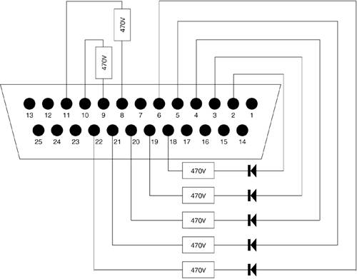
For input operations, we will jumper D7 (pin 9) to Acknowledge (pin 10) and D6 (pin 8) to Busy (pin 11) with 470 ohm resistors. To monitor output, we drive LEDs with data pins D0 through D4 by using a 470 ohm current limiting resistor. We can do this by using an old printer cable or a 25-pin male D-Shell connector from a local electronics store.
NOTE
A good register-level programmer should always know as much about the underlying hardware as possible. This includes finding the datasheet for your particular parallel port I/O device. In the datasheet, you can find the sink/source current limitations for your device. Many Web sites feature interface methods to the parallel port, including isolation, expanding the number of signals, and pull-up and pull-down resistors. They are a must read for any I/O controller work beyond the scope of this example.
This module addresses the parallel port by way of the outb() and inb() functions. Recall from Chapter 2, "Exploration Toolkit," that, depending on the platform compilation, these functions correctly implement the in and out instructions for x86 and the lbz and stb instructions for the memory-mapped I/O of the PowerPC. This inline code can be found in the /io.h file under the appropriate platform.
Parallel Port Software
The following discussion focuses on the pertinent driver functions for this project. The complete program listing for parll.c, along with Make and parll.h files, is included at the end of this book.
1. Setting Up the File Operations (fops)
As previously mentioned, this module uses open(), close(), and ioctl(), as well as the init and cleanup operations discussed in previous projects.
The first step is to set up our file operations structure. This structure defined in /linux/fs.h lists the possible functions we can choose to implement in our module. We do not have to itemize each operationonly the ones we want. A Web search of C99 and linux module furnishes more information on this methodology. By using this structure, we inform the kernel of the location of our implementation (or entry points) of open, release, and ioctl.
 -------------------------------------------------------------------------
 parll.c
 struct file_operations parlport_fops = {
      .open =   parlport_open,
      .ioctl =  parlport_ioctl,
      .release =  parlport_close };

 -------------------------------------------------------------------------
Next, we create the functions open() and close(). These are essentially dummy functions used to flag when we have opened and closed:
 -------------------------------------------------------------------------
 parll.c

 static int parlport_open(struct inode *ino, struct file *filp)
 {
   printk("\n parlport open function");
   return 0;
 }

 static int parlport_close(struct inode *ino, struct file *filp)
 {
   printk("\n parlport close function");
   return 0;
 }

 -------------------------------------------------------------------------
Create the ioctl() function. Note the following declarations were made at the beginning of parll.c:
 -------------------------------------------------------------------------
 #define MODULE_NAME  "parll"
 static int base = 0x378;


 parll.c
 static int parlport_ioctl(struct inode *ino, struct file *filp,
      unsigned int ioctl_cmd, unsigned long parm)
 {
   printk("\n parlport ioctl function");
   if(_IOC_TYPE(ioctl_cmd) != IOCTL_TYPE)
   {
    printk("\n%s wrong ioctl type",MODULE_NAME);
    return -1;
   }
   switch(ioctl_cmd)
   {
    case DATA_OUT:
     printk("\n%s ioctl data out=%x",MODULE_NAME,(unsigned int)parm);
     outb(parm & 0xff, base+0);
     return (parm & 0xff);

    case GET_STATUS:
     parm = inb(base+1);
     printk("\n%s ioctl get status=%x",MODULE_NAME,(unsigned int)parm);
     return parm;

    case CTRL_OUT:
     printk("\n%s ioctl ctrl out=%x",MODULE_NAME,(unsigned int)parm);
     outb(parm && 0xff, base+2);
     return 0;

   }  //end switch
   return 0;
 } //end ioctl

 -------------------------------------------------------------------------
The ioctl() function is made available to handle any user-defined command. In our module, we surface the three registers associated with the parallel port to the user. The DATA_OUT command sends a value to the data register, the GET_STATUS command reads from the status register, and finally, the CTRL_OUT command is available to set the control signals to the port. Although a better methodology would be to hide the device specifics behind the read() and write() routines, this module is mainly for experimentation with I/O, not data encapsulation.
The three commands just used are defined in the header file parll.h. They are created by using the IOCTL helper routines for type checking. Rather than using an integer to represent an IOCTL function, we use the IOCTL type checking macro IO(type,number), where the type is defined as p (for parallel port) and number is the actual IOCTL number used in the case statement. At the beginning of parlport_ioctl(), we check the type, which should be p. Because the application code uses the same header file as the driver, the interface will be consistent.
2. Setting Up the Module Initialization Routine
The initialization module is used to associate the module with the operating system. It can also be used for early initialization of any data structures if desired. Since the parallel port driver requires no complex data structures, we simply register the module.
 -------------------------------------------------------------------------
 parll.c
 static int parll_init(void)
 {
   int retval;

   retval= register_chrdev(Major, MODULE_NAME, &parlport_fops);
   if(retval < 0)
   {
    printk("\n%s: can't register",MODULE_NAME);
    return retval;
   }
   else
   {
    Major=retval;
    printk("\n%s:registered, Major=%d",MODULE_NAME,Major);

    if(request_region(base,3,MODULE_NAME))
     printk("\n%s:I/O region busy.",MODULE_NAME);

   }
   return 0;
 }
 -------------------------------------------------------------------------
The init_module() function is responsible for registering the module with the kernel. The register_chrdev() function takes in the requested major number (discussed in Section 5.2 and later in Chapter 10; if 0, the kernel assigns one to the module). Recall that the major number is kept in the inode structure, which is pointed to by the dentry structure, which is pointed to by a file struct. The second parameter is the name of the device as it will appear in /proc/devices. The third parameter is the file operations structure that was just shown.
Upon successfully registering, our init routine calls request_region() with the base address of the parallel port and the length (in bytes) of the range of registers we are interested in.
The init_module() function returns a negative number upon failure.
3. Setting Up the Module Cleanup Routine
The cleanup_module() function is responsible for unregistering the module and releasing the I/O range that we requested earlier:
 -------------------------------------------------------------------------
 parll.c

 static void parll_cleanup( void )
 {
    printk("\n%s:cleanup ",MODULE_NAME);
    release_region(base,3);
    unregister_chrdev(Major,MODULE_NAME);
 }
 -------------------------------------------------------------------------
Finally, we include the required init and cleanup entry points.
 -----------------------------------------------------------------------
 parll.c
 module_init(parll_init);
 module_exit(parll_cleanup);
 -----------------------------------------------------------------------
4. Inserting the Module
We can now insert our module into the kernel, as in the previous projects, by using
Lkp:~# insmod parll.ko
Looking at /var/log/messages shows us our init() routine output as before, but make specific note of the major number returned.
In previous projects, we simply inserted and removed our module from the kernel. We now need to associate our module with the filesystem with the mknod command. From the command line, enter the following:
Lkp:~# mknod /dev/parll c <XXX> 0
The parameters:
c.
Create a character special file (as opposed to block)
/dev/parll.
The path to our device (for the open call)
XXX.
The major number returned at init time (from /var/log/messages)
0.
The minor number of our device (not used in this example)
For example, if you saw a major number of 254 in /var/log/messages, the command would look like this:
Lkp:~# mknod /dev/parll c 254 0
5. Application Code
Here, we created a simple application that opens our module and starts a binary count on the D0 through D7 output pins.
Compile this code with gcc app.c. The executable output defaults to a.out:
 -------------------------------------------------------------------------
 app.c
 000  //application to use parallel port driver

 #include <fcntl.h>
 #include <linux/ioctl.h>
 004  #include "parll.h"

 main()
 {
   int fptr;
   int i,retval,parm =0;

   printf("\nopening driver now");
 012   if((fptr = open("/dev/parll",O_WRONLY))<0)
   {
    printf("\nopen failed, returned=%d",fptr);
    exit(1);
   }


 018   for(i=0;i<0xff;i++)
   {
 020    system("sleep .2");
 021    retval=ioctl(fptr,DATA_OUT,parm);
 022    retval=ioctl(fptr,GET_STATUS,parm);

 024    if(!(retval & 0x80))
     printf("\nBusy signal count=%x",parm);
    if(retval & 0x40)
 027     printf("\nAck signal count=%x",parm);
 028  //   if(retval & 0x20)
 //    printf("\nPaper end signal count=%x",parm);
 //   if(retval & 0x10)
 //    printf("\nSelect signal count=%x",parm);
 //   if(retval & 0x08)
 033  //    printf("\nError signal count=%x",parm);

    parm++;
   }

 038   close(fptr);

 }
 -------------------------------------------------------------------------
Line 4
The header file common to both the application and the driver contains the new IOCTL helper macros for type checking.
Line 12
Open the driver to get a file handle for our module.
Line 18
Enter the loop.
Line 20
Slow down the loop so we can watch the lights/count.
Line 21
Using the file pointer, send a DATA_OUT command to the module, which in turn uses outb() to write the least significant 8 bits of the parameter to the data port.
Line 22
Read the status byte by way of the ioctl with a GET_STATUS command. This uses inb() and returns the value.
Lines 2427
Watch for our particular bits of interest. Note that Busy* is an active low signal, so when the I/O is off, we read this as true.
Lines 2833
Uncomment these as you improve on the design.
Line 38
Close our module.
If you have built the connector as outlined in Figure 5.5, the busy and ack signals come on when the two most significant bits of the count are on. The application code reads these bits and outputs accordingly.
We just outlined the major elements for a character device driver. By knowing these functions, it is easier to trace through working code or create your own driver. Adding an interrupt handler to this module involves a call to request_irq() and passing in the desired IRQ and the name of the handler. This would be included in the init_module().
Here are some suggested additions to the driver:
|
|

 LINUX
LINUX 
 Books
Books