-
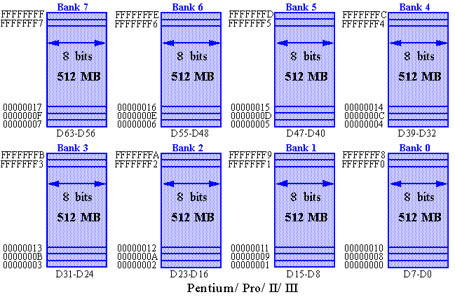
The Pentium bus architecture is not this simple.
-
We will elaborate on this later.
-
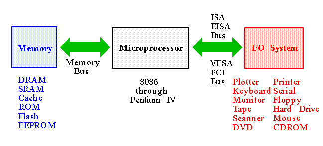
Bus Architecture: Three buses:
-
Address:
-
If I/O, a value between 0000H and FFFFH is issued.
-
If memory, it depends on the architecture:
-
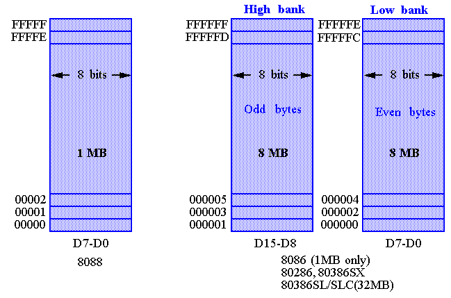
20
-bits (8086/8088)
-
24
-bits (80286/80386SX)
-
25
-bits (80386SL/SLC/EX)
-
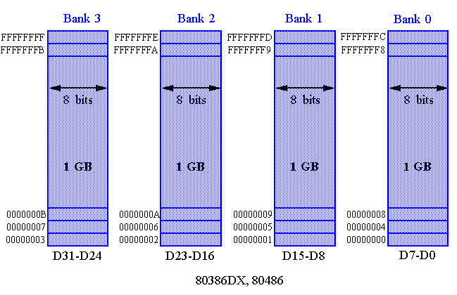
32
-bits (80386DX/80486/Pentium)
-
36
-bits (Pentium Pro/II/III)
-
Data:
-
8
-bits (8088)
-
16
-bits (8086/80286/80386SX/SL/SLC/EX)
-
32
-bits (80386DX/80486/Pentium)
-
64
-bits (Pentium/Pro/II/III)
-
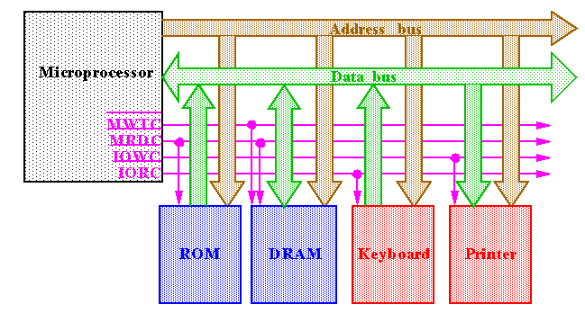
Control:
-
Most systems have at least 4 control bus connections (active low).
-
MRDC
(Memory ReaD Control),
MWRC
,
IORC
(I/O Read Control),
IOWC
.
-
Bus Standards:
-
ISA
(Industry Standard Architecture): 8 MHz
-
8-bit (8086/8088)
-
16-bit (80286-Pentium)
-
EISA
: 8 MHz
-
32-bit (older 386 and 486 machines).
-
PCI
(Peripheral Component Interconnect): 33 MHz
-
32-bit or 64-bit (Pentiums)
-
VESA
(Video Electronic Standards Association): Runs at processor speed.
-
32-bit or 64-bit (Pentiums)
-
Only disk and video. Competes with the PCI but is not popular.
-
Bus Standards:
-
USB
(Universal Serial Bus): 10 Mbps (extensions to 100Mbps)
-
Newest systems.
-
Serial connection to microprocessor.
-
For keyboards, the mouse, modems and sound cards.
-
To reduce system cost through fewer wires.
-
AGP
(Advanced Graphics Port): 66MHz
-
Newest systems.
-
Fast parallel connection: Across 64-bits for 533MB/sec.
-
For video cards.
-
To accommodate the new
DVD
(Digital Versatile Disk) players.
-
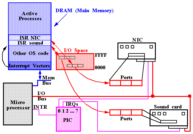
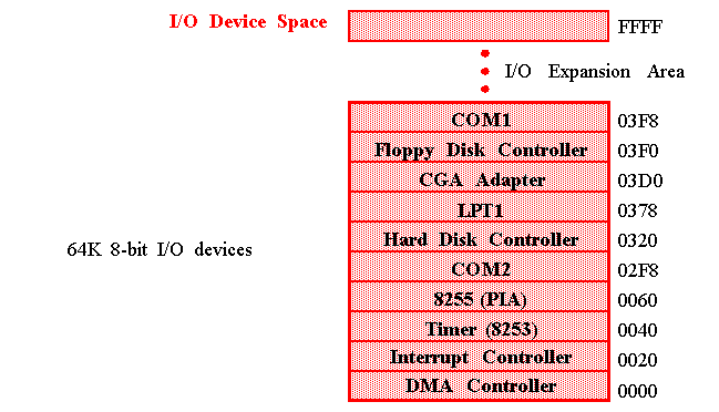
It is important to notice that these I/O addresses are NOT memory-mapped addresses on the 80x86 machines.
-
Special instructions (IN/OUT) are used to communicate to the I/O devices.
-
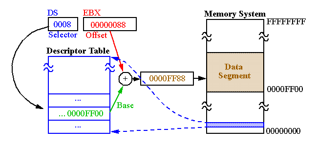
Segments are
interpreted
differently in Protected Mode vs. Real Mode:
-
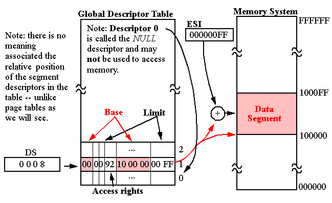
Segment register contains a
selector
that selects a
descriptor
from the descriptor table.
-
The
descriptor
contains information about the segment, e.g., it's base address, length and access rights.
-
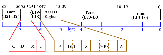
The offset can be 32-bits.
-
Base address
:
-
Starting location of the memory segment.
-
Limit
:
-
Length of the segment minus 1.
-
20-bits allows segments up to 1 MB.
-
This value is shifted by 12 bits to the left when the G (Granularity bit) is set to 1.
-
Segment Descriptors: Bits 52-55
-
G bit
:
-
When G=0, segments can be 1 byte to 1MB in length.
-
When G=1, segments can be 4KB to 4GB in length.
-
D bit
:
-
Indicates how the instructions (80386 and up) access register and memory data in protected mode.
-
When D=0, instructions are 16-bit instructions,
with 16-bit offsets and 16-bit registers. Stacks are assumed 16-bit
wide and SP is used.
-
When D=1, 32-bits are assumed.
-
Allows 8086-80286 programs to run.
-
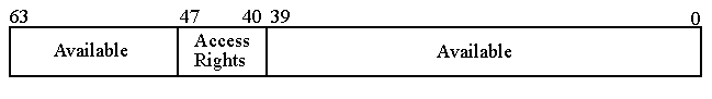
Segment Descriptors: Access Rights (Byte 5):
-
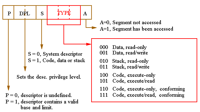
The Access Rights (AR) byte controls access to a protected mode segment and how the segment functions in the system.
-
Details:
-
The
A
(accessed) bit is set automatically by the microprocessor and is never cleared.
-
This allows OS code to track frequency of usage.
-
The
P
(present) bit should be interpreted as "descriptor-is-valid".
-
If this bit is 0, the microprocessor will
refuse
any attempts to use this descriptor in an instruction.
-
Although the AR must always be valid, when P=0, the rest of the descriptor can be used in any way the OS likes.
-
The
S
(system) bit indicates how the descriptor is to be interpreted.
-
S=1 indicates a system descriptor (more on this later).
-
S=0 indicates a code, data or stack descriptor.
-
Details:
-
Non-system (
S
=0) segments:
-
Type=0: The data segment is basically a ROM.
-
Type=1: Both read and write operations allowed.
-
Code can
NOT
be fetched and executed from either of these segment types.
-
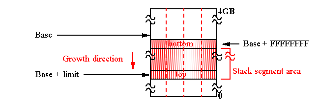
Type=2 or 3: A stack segment is defined analogously to Types 0 and 1.
-
However, the interpretation of the limit field is different.
-
In this case, all offsets must be
greater
than the limit.
-
The upper limit is set to base address + FFFF (with D=0) or base address + FFFFFFFF (with D=1).
-
This means the stack segment
ends 1 byte
below
the base address.
-
Expanding of the stack segment simply involves
decreasing
the limit.
-
Type=4: A code segment with no read permission.
-
This means no constants are allowed, since they cannot be read out.
-
Type=5: A code segment in which constants may be embedded.
-
In either case, no writing (self-modifying code) is permitted.
-
Type=6 and 7: Analogous to Types 4 and 5
without
privilege protection.
-
We'll discuss the meaning of "conforming" soon.
-
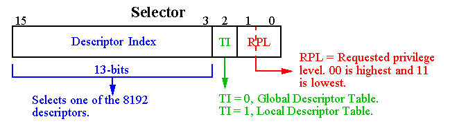
Descriptor Index and Table Index (TI)
:
-
The 13 bit descriptor index selects one of up to 8K descriptors in either the GDT and LDT, as specified by the TI bit.
-
Therefore, these 14 bits allows access to 16K 8-byte descriptors.
-
RPL
:
-
The desired privilege level of the program.
-
Access is granted if the RPL value is lower (higher in privilege) than
the AR of the segment. Otherwise, a privilege violation is issued.
-
So instead of left shifting by 4 bits in Real Mode to form the segment
address, we right shift by 3 bits and use the value as a table index.
-
There are actually three different descriptor tables,
GDT
,
LDT
and
IDT
.
-
Exactly one
GDT
and
IDT
must be defined for Protected Mode operation.
-
Global Descriptor Table (
GDT
).
-
The GDT is used by all programs.
-
Local Descriptor Table (
LDT
).
-
An LDT can optionally be defined on a per-task basis and is used to expand the addressable range of the task.
-
Interrupt Descriptor Table (
IDT
).
-
The IDT is a direct replacement to the interrupt vector table used in 8086 systems.
-
Note that references to
IDT
are done through the
hardware interrupt mechanism
, and not from a program via a selector.
-
Programmer
invisible
registers:
-
The
GDT
and
IDT
(and LDT) are located in the memory system.
-
The addresses of the GDT and IDT and their limits (up to 64K bytes) are loaded in special registers,
GDTR
and
IDTR, before switching to Protected Mode is possible.
-
Programmer
invisible
registers:
-
The other registers enclosed by the red-dotted line are part of the descriptor cache.
-
The
cache
is used to reduce the number of actual memory references needed to construct the physical address.
-
There is one cache register for each of the 6 segment registers, CS,
DS, etc. and the LDTR (Local Descriptor Table Register) and TR (Task
Register) selectors.
-
The base address, limit and access rights of the descriptor are loaded from memory every time the corresponding
selector
changes.
-
The LDTR and TR selectors refer to special
system
descriptors in the GDT.
-
These registers provide hardware acceleration support for task switching.
-
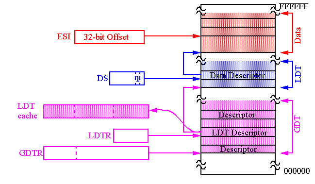
Let's first consider how LDTs are used to extend the address space of individual tasks.
-
The LDTR
selector
indexes a GDT
system
descriptor describing the segment containing the LDT while the
cache
stores the actual LDT descriptor.
-
The LDTR selector can be loaded with a new value when another task is run.
-
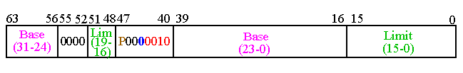
Bit 44: The S flag is clear to indicate an LDT descriptor.
-
Bit 40-43: The Type field is extended to 4 bits (no Accessed bit). Type 2 (0010) indicates a LDT descriptor.
-
Bit 47: If the Present bit is not set (e.g. there is no LDT defined),
the 80x86 will not allow you to load the LDTR with its selector.
-
Bit 0-15, 16-19: Although the limit is still 20 bits (and the G bit is also valid), segments larger than 64KB don't make sense!
|
| beat | Здравствуйте, не подскажете, как считать информацию с isa-порта в языке python?
2007-07-18 21:37:38 | |
|
|

 LINUX
LINUX 
 Languages