1.6. An Overview of Unix Kernels
Unix kernels provide an execution environment in which applications may run. Therefore, the kernel must implement a set of services and corresponding interfaces. Applications use those interfaces and do not usually interact directly with hardware resources.
1.6.1. The Process/Kernel Model
As already mentioned, a CPU can run in either User Mode
or Kernel Mode
. Actually, some CPUs can have more than two execution states. For instance, the 80 x 86 microprocessors have four different execution states. But all standard Unix kernels use only Kernel Mode and User Mode.
When a program is executed in User Mode, it cannot directly access the kernel data structures or the kernel programs. When an application executes in Kernel Mode, however, these restrictions no longer apply. Each CPU model provides special instructions to switch from User Mode to Kernel Mode and vice versa. A program usually executes in User Mode and switches to Kernel Mode only when requesting a service provided by the kernel. When the kernel has satisfied the program's request, it puts the program back in User Mode.
Processes are dynamic entities that usually have a limited life span within the system. The task of creating, eliminating, and synchronizing the existing processes
is delegated to a group of routines in the kernel.
The kernel itself is not a process but a process manager. The process/kernel model assumes that processes that require a kernel service use specific programming constructs called system calls
. Each system call sets up the group of parameters that identifies the process request and then executes the hardware-dependent CPU instruction to switch from User Mode to Kernel Mode.
Besides user processes, Unix systems include a few privileged processes called kernel threads
with the following characteristics:
They run in Kernel Mode in the kernel address space. They do not interact with users, and thus do not require terminal devices. They are usually created during system startup and remain alive until the system is shut down.
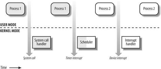
On a uniprocessor system, only one process is running at a time, and it may run either in User or in Kernel Mode. If it runs in Kernel Mode, the processor is executing some kernel routine. Figure 1-2 illustrates examples of transitions between User and Kernel Mode. Process 1 in User Mode issues a system call, after which the process switches to Kernel Mode, and the system call is serviced. Process 1 then resumes execution in User Mode until a timer interrupt occurs, and the scheduler is activated in Kernel Mode. A process switch takes place, and Process 2 starts its execution in User Mode until a hardware device raises an interrupt. As a consequence of the interrupt, Process 2 switches to Kernel Mode and services the interrupt.
Unix kernels do much more than handle system calls; in fact, kernel routines can be activated in several ways:
A process invokes a system call. The CPU executing the process signals an exception, which is an unusual condition such as an invalid instruction. The kernel handles the exception on behalf of the process that caused it. A peripheral device issues an interrupt signal to the CPU to notify it of an event such as a request for attention, a status change, or the completion of an I/O operation. Each interrupt signal is dealt by a kernel program called an interrupt handler. Because peripheral devices operate asynchronously with respect to the CPU, interrupts occur at unpredictable times. A kernel thread is executed. Because it runs in Kernel Mode, the corresponding program must be considered part of the kernel.
1.6.2. Process Implementation
To let the kernel manage processes, each process is represented by a process descriptor that includes information about the current state of the process.
When the kernel stops the execution of a process, it saves the current contents of several processor registers in the process descriptor. These include:
The program counter (PC) and stack pointer (SP) registers The general purpose registers The floating point registers The processor control registers (Processor Status Word) containing information about the CPU state The memory management registers used to keep track of the RAM accessed by the process
When the kernel decides to resume executing a process, it uses the proper process descriptor fields to load the CPU registers. Because the stored value of the program counter points to the instruction following the last instruction executed, the process resumes execution at the point where it was stopped.
When a process is not executing on the CPU, it is waiting for some event. Unix kernels distinguish many wait states, which are usually implemented by queues of process descriptors
; each (possibly empty) queue corresponds to the set of processes waiting for a specific event.
1.6.3. Reentrant Kernels
All Unix kernels are reentrant. This means that several processes may be executing in Kernel Mode at the same time. Of course, on uniprocessor systems, only one process can progress, but many can be blocked in Kernel Mode when waiting for the CPU or the completion of some I/O operation. For instance, after issuing a read to a disk on behalf of a process, the kernel lets the disk controller handle it and resumes executing other processes. An interrupt notifies the kernel when the device has satisfied the read, so the former process can resume the execution.
One way to provide reentrancy is to write functions so that they modify only local variables and do not alter global data structures. Such functions are called reentrant functions
. But a reentrant kernel is not limited only to such reentrant functions (although that is how some real-time kernels are implemented). Instead, the kernel can include nonreentrant functions and use locking mechanisms to ensure that only one process can execute a nonreentrant function at a time.
If a hardware interrupt occurs, a reentrant kernel is able to suspend the current running process even if that process is in Kernel Mode. This capability is very important, because it improves the throughput of the device controllers that issue interrupts. Once a device has issued an interrupt, it waits until the CPU acknowledges it. If the kernel is able to answer quickly, the device controller will be able to perform other tasks while the CPU handles the interrupt.
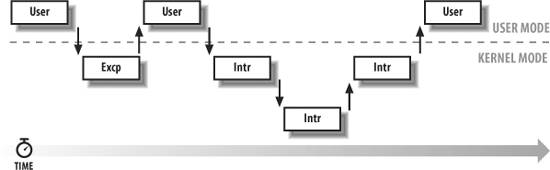
Now let's look at kernel reentrancy and its impact on the organization of the kernel. A kernel control path denotes the sequence of instructions executed by the kernel to handle a system call, an exception, or an interrupt.
In the simplest case, the CPU executes a kernel control path sequentially from the first instruction to the last. When one of the following events occurs, however, the CPU interleaves the kernel control paths
:
A process executing in User Mode invokes a system call, and the corresponding kernel control path verifies that the request cannot be satisfied immediately; it then invokes the scheduler to select a new process to run. As a result, a process switch occurs. The first kernel control path is left unfinished, and the CPU resumes the execution of some other kernel control path. In this case, the two control paths are executed on behalf of two different processes. The CPU detects an exceptionfor example, access to a page not present in RAMwhile running a kernel control path. The first control path is suspended, and the CPU starts the execution of a suitable procedure. In our example, this type of procedure can allocate a new page for the process and read its contents from disk. When the procedure terminates, the first control path can be resumed. In this case, the two control paths are executed on behalf of the same process. A hardware interrupt occurs while the CPU is running a kernel control path with the interrupts enabled. The first kernel control path is left unfinished, and the CPU starts processing another kernel control path to handle the interrupt. The first kernel control path resumes when the interrupt handler terminates. In this case, the two kernel control paths run in the execution context of the same process, and the total system CPU time is accounted to it. However, the interrupt handler doesn't necessarily operate on behalf of the process. An interrupt occurs while the CPU is running with kernel preemption enabled, and a higher priority process is runnable. In this case, the first kernel control path is left unfinished, and the CPU resumes executing another kernel control path on behalf of the higher priority process. This occurs only if the kernel has been compiled with kernel preemption support.
Figure 1-3 illustrates a few examples of noninterleaved and interleaved kernel control paths. Three different CPU states are considered:
Running a process in User Mode (User) Running an exception or a system call handler (Excp) Running an interrupt handler (Intr)
1.6.4. Process Address Space
Each process runs in its private address space. A process running in User Mode refers to private stack, data, and code areas. When running in Kernel Mode, the process addresses the kernel data and code areas and uses another private stack.
Because the kernel is reentrant, several kernel control pathseach related to a different processmay be executed in turn. In this case, each kernel control path refers to its own private kernel stack.
While it appears to each process that it has access to a private address space, there are times when part of the address space is shared among processes. In some cases, this sharing is explicitly requested by processes; in others, it is done automatically by the kernel to reduce memory usage.
If the same program, say an editor, is needed simultaneously by several users, the program is loaded into memory only once, and its instructions can be shared by all of the users who need it. Its data, of course, must not be shared, because each user will have separate data. This kind of shared address space is done automatically by the kernel to save memory.
Processes also can share parts of their address space as a kind of interprocess communication, using the "shared memory" technique introduced in System V
and supported by Linux.
Finally, Linux supports the mmap( )
system call, which allows part of a file or the information stored on a block device to be mapped into a part of a process address space. Memory mapping can provide an alternative to normal reads and writes for transferring data. If the same file is shared by several processes, its memory mapping is included in the address space of each of the processes that share it.
1.6.5. Synchronization and Critical Regions
Implementing a reentrant kernel requires the use of synchronization
. If a kernel control path is suspended while acting on a kernel data structure, no other kernel control path should be allowed to act on the same data structure unless it has been reset to a consistent state. Otherwise, the interaction of the two control paths could corrupt the stored information.
For example, suppose a global variable V contains the number of available items of some system resource. The first kernel control path, A, reads the variable and determines that there is just one available item. At this point, another kernel control path, B, is activated and reads the same variable, which still contains the value 1. Thus, B decreases V and starts using the resource item. Then A resumes the execution; because it has already read the value of V, it assumes that it can decrease V and take the resource item, which B already uses. As a final result, V contains -1, and two kernel control paths use the same resource item with potentially disastrous effects.
When the outcome of a computation depends on how two or more processes are scheduled, the code is incorrect. We say that there is a race condition.
In general, safe access to a global variable is ensured by using atomic operations
. In the previous example, data corruption is not possible if the two control paths read and decrease V with a single, noninterruptible operation. However, kernels contain many data structures that cannot be accessed with a single operation. For example, it usually isn't possible to remove an element from a linked list with a single operation, because the kernel needs to access at least two pointers at once. Any section of code that should be finished by each process that begins it before another process can enter it is called a critical region.
These problems occur not only among kernel control paths but also among processes sharing common data. Several synchronization techniques have been adopted. The following section concentrates on how to synchronize kernel control paths.
1.6.5.1. Kernel preemption disabling
To provide a drastically simple solution to synchronization problems, some traditional Unix kernels are nonpreemptive: when a process executes in Kernel Mode, it cannot be arbitrarily suspended and substituted with another process. Therefore, on a uniprocessor system, all kernel data structures that are not updated by interrupts or exception handlers
are safe for the kernel to access.
Of course, a process in Kernel Mode can voluntarily relinquish the CPU, but in this case, it must ensure that all data structures are left in a consistent state. Moreover, when it resumes its execution, it must recheck the value of any previously accessed data structures that could be changed.
A synchronization mechanism applicable to preemptive kernels consists of disabling
kernel preemption before entering a critical region and reenabling it right after leaving the region.
Nonpreemptability is not enough for multiprocessor systems, because two kernel control paths running on different CPUs can concurrently access the same data structure.
1.6.5.2. Interrupt disabling
Another synchronization mechanism for uniprocessor systems consists of disabling all hardware interrupts before entering a critical region and reenabling them right after leaving it. This mechanism, while simple, is far from optimal. If the critical region is large, interrupts can remain disabled for a relatively long time, potentially causing all hardware activities to freeze.
Moreover, on a multiprocessor system, disabling interrupts on the local CPU is not sufficient, and other synchronization techniques must be used.
1.6.5.3. Semaphores
A widely used mechanism, effective in both uniprocessor and multiprocessor systems, relies on the use of semaphores
. A semaphore is simply a counter associated with a data structure; it is checked by all kernel threads before they try to access the data structure. Each semaphore may be viewed as an object composed of:
The down( ) method decreases the value of the semaphore. If the new value is less than 0, the method adds the running process to the semaphore list and then blocks (i.e., invokes the scheduler). The up( ) method increases the value of the semaphore and, if its new value is greater than or equal to 0, reactivates one or more processes in the semaphore list.
Each data structure to be protected has its own semaphore, which is initialized to 1. When a kernel control path wishes to access the data structure, it executes the down( ) method on the proper semaphore. If the value of the new semaphore isn't negative, access to the data structure is granted. Otherwise, the process that is executing the kernel control path is added to the semaphore list and blocked. When another process executes the up( ) method on that semaphore, one of the processes in the semaphore list is allowed to proceed.
1.6.5.4. Spin locks
In multiprocessor systems, semaphores are not always the best solution to the synchronization problems. Some kernel data structures should be protected from being concurrently accessed by kernel control paths that run on different CPUs. In this case, if the time required to update the data structure is short, a semaphore could be very inefficient. To check a semaphore, the kernel must insert a process in the semaphore list and then suspend it. Because both operations are relatively expensive, in the time it takes to complete them, the other kernel control path could have already released the semaphore.
In these cases, multiprocessor operating systems use spin locks
. A spin lock is very similar to a semaphore, but it has no process list; when a process finds the lock closed by another process, it "spins" around repeatedly, executing a tight instruction loop until the lock becomes open.
Of course, spin locks are useless in a uniprocessor environment. When a kernel control path tries to access a locked data structure, it starts an endless loop. Therefore, the kernel control path that is updating the protected data structure would not have a chance to continue the execution and release the spin lock. The final result would be that the system hangs.
1.6.5.5. Avoiding deadlocks
Processes or kernel control paths that synchronize with other control paths may easily enter a deadlock state. The simplest case of deadlock occurs when process p1 gains access to data structure a and process p2 gains access to b, but p1 then waits for b and p2 waits for a. Other more complex cyclic waits among groups of processes also may occur. Of course, a deadlock condition causes a complete freeze of the affected processes or kernel control paths.
As far as kernel design is concerned, deadlocks become an issue when the number of kernel locks used is high. In this case, it may be quite difficult to ensure that no deadlock state will ever be reached for all possible ways to interleave kernel control paths. Several operating systems, including Linux, avoid this problem by requesting locks in a predefined order.
1.6.6. Signals and Interprocess Communication
Unix signals
provide a mechanism for notifying processes of system events. Each event has its own signal number, which is usually referred to by a symbolic constant such as SIGTERM. There are two kinds of system events:
Asynchronous notifications For instance, a user can send the interrupt signal SIGINT to a foreground process by pressing the interrupt keycode (usually Ctrl-C) at the terminal.
Synchronous notifications For instance, the kernel sends the signal SIGSEGV to a process when it accesses a memory location at an invalid address.
The POSIX standard defines about 20 different signals, 2 of which are user-definable and may be used as a primitive mechanism for communication and synchronization among processes in User Mode. In general, a process may react to a signal delivery in two possible ways:
If the process does not specify one of these alternatives, the kernel performs a default action that depends on the signal number. The five possible default actions
are:
Terminate the process. Write the execution context and the contents of the address space in a file (core dump) and terminate the process. Ignore the signal. Suspend the process. Resume the process's execution, if it was stopped.
Kernel signal handling is rather elaborate, because the POSIX semantics allows processes to temporarily block signals. Moreover, the SIGKILL and SIGSTOP signals cannot be directly handled by the process or ignored.
AT&T's Unix System V
introduced other kinds of interprocess communication among processes in User Mode, which have been adopted by many Unix kernels: semaphores
, message queues
, and shared memory
. They are collectively known as System V IPC.
The kernel implements these constructs as IPC resources. A process acquires a resource by invoking a shmget( )
, semget( )
, or msgget( )
system call. Just like files, IPC resources are persistent: they must be explicitly deallocated by the creator process, by the current owner, or by a superuser process.
Semaphores are similar to those described in the section "Synchronization and Critical Regions," earlier in this chapter, except that they are reserved for processes in User Mode. Message queues allow processes to exchange messages by using the msgsnd( )
and msgrcv( )
system calls, which insert a message into a specific message queue and extract a message from it, respectively.
The POSIX standard (IEEE Std 1003.1-2001) defines an IPC mechanism based on message queues, which is usually known as POSIX message queues
. They are similar to the System V IPC's message queues, but they have a much simpler file-based interface to the applications.
Shared memory provides the fastest way for processes to exchange and share data. A process starts by issuing a shmget( ) system call to create a new shared memory having a required size. After obtaining the IPC resource identifier, the process invokes the shmat( )
system call, which returns the starting address of the new region within the process address space. When the process wishes to detach the shared memory from its address space, it invokes the shmdt( )
system call. The implementation of shared memory depends on how the kernel implements process address spaces.
1.6.7. Process Management
Unix makes a neat distinction between the process and the program it is executing. To that end, the fork( )
and _exit( )
system calls are used respectively to create a new process and to terminate it, while an exec( )-like system call is invoked to load a new program. After such a system call is executed, the process resumes execution with a brand new address space containing the loaded program.
The process that invokes a fork( ) is the parent, while the new process is its child. Parents and children can find one another because the data structure describing each process includes a pointer to its immediate parent and pointers to all its immediate children.
A naive implementation of the fork( ) would require both the parent's data and the parent's code to be duplicated and the copies assigned to the child. This would be quite time consuming. Current kernels that can rely on hardware paging units follow the Copy-On-Write approach, which defers page duplication until the last moment (i.e., until the parent or the child is required to write into a page). We shall describe how Linux implements this technique in the section "Copy On Write" in Chapter 9.
The _exit( ) system call terminates a process. The kernel handles this system call by releasing the resources owned by the process and sending the parent process a SIGCHLD signal, which is ignored by default.
1.6.7.1. Zombie processes
How can a parent process inquire about termination of its children? The wait4( )
system call allows a process to wait until one of its children terminates; it returns the process ID (PID) of the terminated child.
When executing this system call, the kernel checks whether a child has already terminated. A special zombie process state is introduced to represent terminated processes: a process remains in that state until its parent process executes a wait4( ) system call on it. The system call handler extracts data about resource usage from the process descriptor fields; the process descriptor may be released once the data is collected. If no child process has already terminated when the wait4( ) system call is executed, the kernel usually puts the process in a wait state until a child terminates.
Many kernels also implement a waitpid( )
system call, which allows a process to wait for a specific child process. Other variants of wait4( ) system calls are also quite common.
It's good practice for the kernel to keep around information on a child process until the parent issues its wait4( ) call, but suppose the parent process terminates without issuing that call? The information takes up valuable memory slots that could be used to serve living processes. For example, many shells allow the user to start a command in the background and then log out. The process that is running the command shell terminates, but its children continue their execution.
The solution lies in a special system process called init, which is created during system initialization. When a process terminates, the kernel changes the appropriate process descriptor pointers of all the existing children of the terminated process to make them become children of init. This process monitors the execution of all its children and routinely issues wait4( ) system calls, whose side effect is to get rid of all orphaned zombies.
1.6.7.2. Process groups and login sessions
Modern Unix operating systems introduce the notion of process groups
to represent a "job" abstraction. For example, in order to execute the command line:
$ ls | sort | more
a shell that supports process groups, such as bash, creates a new group for the three processes corresponding to ls, sort, and more. In this way, the shell acts on the three processes as if they were a single entity (the job, to be precise). Each process descriptor includes a field containing the process group ID
. Each group of processes may have a group leader, which is the process whose PID coincides with the process group ID. A newly created process is initially inserted into the process group of its parent.
Modern Unix kernels also introduce login sessions. Informally, a login session contains all processes that are descendants of the process that has started a working session on a specific terminalusually, the first command shell process created for the user. All processes in a process group must be in the same login session. A login session may have several process groups active simultaneously; one of these process groups is always in the foreground, which means that it has access to the terminal. The other active process groups are in the background. When a background process tries to access the terminal, it receives a SIGTTIN or SIGTTOUT signal. In many command shells, the internal commands bg and fg can be used to put a process group in either the background or the foreground.
1.6.8. Memory Management
Memory management is by far the most complex activity in a Unix kernel. More than a third of this book is dedicated just to describing how Linux handles memory management. This section illustrates some of the main issues related to memory management.
1.6.8.1. Virtual memory
All recent Unix systems provide a useful abstraction called virtual memory
. Virtual memory acts as a logical layer between the application memory requests and the hardware Memory Management Unit
(MMU). Virtual memory has many purposes and advantages:
Several processes can be executed concurrently. It is possible to run applications whose memory needs are larger than the available physical memory. Processes can execute a program whose code is only partially loaded in memory. Each process is allowed to access a subset of the available physical memory. Processes can share a single memory image of a library or program. Programs can be relocatable that is, they can be placed anywhere in physical memory. Programmers can write machine-independent code, because they do not need to be concerned about physical memory organization.
The main ingredient of a virtual memory subsystem is the notion of virtual address space. The set of memory references that a process can use is different from physical memory addresses. When a process uses a virtual address, the kernel and the MMU cooperate to find the actual physical location of the requested memory item.
Today's CPUs include hardware circuits that automatically translate the virtual addresses into physical ones. To that end, the available RAM is partitioned into page frames
typically 4 or 8 KB in lengthand a set of Page Tables is introduced to specify how virtual addresses correspond to physical addresses. These circuits make memory allocation simpler, because a request for a block of contiguous virtual addresses can be satisfied by allocating a group of page frames having noncontiguous physical addresses.
1.6.8.2. Random access memory usage
All Unix operating systems clearly distinguish between two portions of the random access memory (RAM). A few megabytes are dedicated to storing the kernel image (i.e., the kernel code and the kernel static data structures). The remaining portion of RAM is usually handled by the virtual memory system and is used in three possible ways:
To satisfy kernel requests for buffers, descriptors, and other dynamic kernel data structures To satisfy process requests for generic memory areas and for memory mapping of files To get better performance from disks and other buffered devices by means of caches
Each request type is valuable. On the other hand, because the available RAM is limited, some balancing among request types must be done, particularly when little available memory is left. Moreover, when some critical threshold of available memory is reached and a page-frame-reclaiming algorithm is invoked to free additional memory, which are the page frames most suitable for reclaiming? As we will see in Chapter 17, there is no simple answer to this question and very little support from theory. The only available solution lies in developing carefully tuned empirical algorithms.
One major problem that must be solved by the virtual memory system is memory fragmentation
. Ideally, a memory request should fail only when the number of free page frames is too small. However, the kernel is often forced to use physically contiguous memory areas. Hence the memory request could fail even if there is enough memory available, but it is not available as one contiguous chunk.
1.6.8.3. Kernel Memory Allocator
The Kernel Memory Allocator (KMA) is a subsystem that tries to satisfy the requests for memory areas from all parts of the system. Some of these requests come from other kernel subsystems needing memory for kernel use, and some requests come via system calls from user programs to increase their processes' address spaces. A good KMA should have the following features:
It must be fast. Actually, this is the most crucial attribute, because it is invoked by all kernel subsystems (including the interrupt handlers). It should minimize the amount of wasted memory. It should try to reduce the memory fragmentation problem. It should be able to cooperate with the other memory management subsystems to borrow and release page frames from them.
Several proposed KMAs, which are based on a variety of different algorithmic techniques, include:
As we will see in Chapter 8, Linux's KMA uses a Slab allocator on top of a buddy system.
1.6.8.4. Process virtual address space handling
The address space of a process contains all the virtual memory addresses that the process is allowed to reference. The kernel usually stores a process virtual address space as a list of memory area descriptors
. For example, when a process starts the execution of some program via an exec( )-like system call, the kernel assigns to the process a virtual address space that comprises memory areas for:
The executable code of the program The initialized data of the program The uninitialized data of the program The initial program stack (i.e., the User Mode stack) The executable code and data of needed shared libraries The heap (the memory dynamically requested by the program)
All recent Unix operating systems adopt a memory allocation strategy called demand paging
. With demand paging, a process can start program execution with none of its pages in physical memory. As it accesses a nonpresent page, the MMU generates an exception; the exception handler finds the affected memory region, allocates a free page, and initializes it with the appropriate data. In a similar fashion, when the process dynamically requires memory by using malloc( ), or the brk( )
system call (which is invoked internally by malloc( )), the kernel just updates the size of the heap memory region of the process. A page frame is assigned to the process only when it generates an exception by trying to refer its virtual memory addresses.
Virtual address spaces also allow other efficient strategies, such as the Copy On Write strategy mentioned earlier. For example, when a new process is created, the kernel just assigns the parent's page frames to the child address space, but marks them read-only. An exception is raised as soon the parent or the child tries to modify the contents of a page. The exception handler assigns a new page frame to the affected process and initializes it with the contents of the original page.
1.6.8.5. Caching
A good part of the available physical memory is used as cache for hard disks and other block devices. This is because hard drives are very slow: a disk access requires several milliseconds, which is a very long time compared with the RAM access time. Therefore, disks are often the bottleneck in system performance. As a general rule, one of the policies already implemented in the earliest Unix system is to defer writing to disk as long as possible. As a result, data read previously from disk and no longer used by any process continue to stay in RAM.
This strategy is based on the fact that there is a good chance that new processes will require data read from or written to disk by processes that no longer exist. When a process asks to access a disk, the kernel checks first whether the required data are in the cache. Each time this happens (a cache hit), the kernel is able to service the process request without accessing the disk.
The sync( )
system call forces disk synchronization by writing all of the "dirty" buffers (i.e., all the buffers whose contents differ from that of the corresponding disk blocks) into disk. To avoid data loss, all operating systems take care to periodically write dirty buffers back to disk.
1.6.9. Device Drivers
The kernel interacts with I/O devices by means of device drivers
. Device drivers are included in the kernel and consist of data structures and functions that control one or more devices, such as hard disks, keyboards, mouses, monitors, network interfaces, and devices connected to an SCSI bus. Each driver interacts with the remaining part of the kernel (even with other drivers) through a specific interface. This approach has the following advantages:
Device-specific code can be encapsulated in a specific module. Vendors can add new devices without knowing the kernel source code; only the interface specifications must be known. The kernel deals with all devices in a uniform way and accesses them through the same interface. It is possible to write a device driver as a module that can be dynamically loaded in the kernel without requiring the system to be rebooted. It is also possible to dynamically unload a module that is no longer needed, therefore minimizing the size of the kernel image stored in RAM.
Figure 1-4 illustrates how device drivers interface with the rest of the kernel and with the processes.
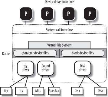
Some user programs (P) wish to operate on hardware devices. They make requests to the kernel using the usual file-related system calls and the device files normally found in the /dev directory. Actually, the device files are the user-visible portion of the device driver interface. Each device file refers to a specific device driver, which is invoked by the kernel to perform the requested operation on the hardware component.
At the time Unix was introduced, graphical terminals were uncommon and expensive, so only alphanumeric terminals were handled directly by Unix kernels. When graphical terminals became widespread, ad hoc applications such as the X Window System
were introduced that ran as standard processes and accessed the I/O ports of the graphics interface and the RAM video area directly. Some recent Unix kernels, such as Linux 2.6, provide an abstraction for the frame buffer of the graphic card and allow application software to access them without needing to know anything about the I/O ports of the graphics interface (see the section "Levels of Kernel Support" in Chapter 13.)
2.1. Memory Addresses
Programmers casually refer to a memory address as the way to access the contents of a memory cell. But when dealing with 80 x 86 microprocessors, we have to distinguish three kinds of addresses:
Logical address Included in the machine language instructions to specify the address of an operand or of an instruction. This type of address embodies the well-known 80 x 86 segmented architecture that forces MS-DOS
and Windows
programmers to divide their programs into segments
. Each logical address consists of a segment and an offset
(or displacement) that denotes the distance from the start of the segment to the actual address.
Linear address (also known as virtual address) A single 32-bit unsigned integer that can be used to address up to 4 GB that is, up to 4,294,967,296 memory cells. Linear addresses are usually represented in hexadecimal notation; their values range from 0x00000000 to 0xffffffff.
Physical address Used to address memory cells in memory chips. They correspond to the electrical signals sent along the address pins of the microprocessor to the memory bus. Physical addresses are represented as 32-bit or 36-bit unsigned integers.
The Memory Management Unit (MMU) transforms a logical address into a linear address by means of a hardware circuit called a segmentation unit
; subsequently, a second hardware circuit called a paging unit
transforms the linear address into a physical address (see Figure 2-1).

In multiprocessor systems, all CPUs usually share the same memory; this means that RAM chips may be accessed concurrently by independent CPUs. Because read or write operations on a RAM chip must be performed serially, a hardware circuit called a memory arbiter is inserted between the bus and every RAM chip. Its role is to grant access to a CPU if the chip is free and to delay it if the chip is busy servicing a request by another processor. Even uniprocessor systems use memory arbiters
, because they include specialized processors called DMA controllers
that operate concurrently with the CPU (see the section "Direct Memory Access (DMA)" in
Chapter 13). In the case of multiprocessor systems, the structure of the arbiter is more complex because it has more input ports. The dual Pentium, for instance, maintains a two-port arbiter at each chip entrance and requires that the two CPUs exchange synchronization messages before attempting to use the common bus. From the programming point of view, the arbiter is hidden because it is managed by hardware circuits.
|
2.2. Segmentation in Hardware
Starting with the 80286
model, Intel microprocessors perform address translation in two different ways called real mode
and protected mode
. We'll focus in the next sections on address translation when protected mode is enabled. Real mode exists mostly to maintain processor compatibility with older models and to allow the operating system to bootstrap (see Appendix A for a short description of real mode).
2.2.1. Segment Selectors and Segmentation Registers
A logical address consists of two parts: a segment identifier and an offset that specifies the relative address within the segment. The segment identifier is a 16-bit field called the Segment Selector (see Figure 2-2), while the offset is a 32-bit field. We'll describe the fields of Segment Selectors in the section "Fast Access to Segment Descriptors" later in this chapter.

To make it easy to retrieve segment selectors
quickly, the processor provides segmentation registers
whose only purpose is to hold Segment Selectors; these registers are called cs, ss, ds, es, fs, and gs. Although there are only six of them, a program can reuse the same segmentation register for different purposes by saving its content in memory and then restoring it later.
Three of the six segmentation registers have specific purposes:
cs The code segment register, which points to a segment containing program instructions
ss The stack segment register, which points to a segment containing the current program stack
ds The data segment register, which points to a segment containing global and static data
The remaining three segmentation registers are general purpose and may refer to arbitrary data segments.
The cs register has another important function: it includes a 2-bit field that specifies the Current Privilege Level (CPL) of the CPU. The value 0 denotes the highest privilege level, while the value 3 denotes the lowest one. Linux uses only levels 0 and 3, which are respectively called Kernel Mode and User Mode.
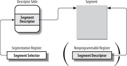
2.2.2. Segment Descriptors
Each segment is represented by an 8-byte Segment Descriptor that describes the segment characteristics. Segment Descriptors are stored either in the Global Descriptor Table (GDT
) or in the Local Descriptor Table(LDT).
Usually only one GDT is defined, while each process is permitted to have its own LDT if it needs to create additional segments besides those stored in the GDT. The address and size of the GDT in main memory are contained in the gdtr
control register, while the address and size of the currently used LDT are contained in the ldtr
control register.
Figure 2-3 illustrates the format of a Segment Descriptor; the meaning of the various fields is explained in Table 2-1.
Table 2-1. Segment Descriptor fieldsField name | Description |
|---|
Base | Contains the linear address of the first byte of the segment. | G | Granularity flag: if it is cleared (equal to 0), the segment size is expressed in bytes; otherwise, it is expressed in multiples of 4096 bytes. | Limit | Holds the offset of the last memory cell in the segment, thus binding the segment length. When G is set to 0, the size of a segment may vary between 1 byte and 1 MB; otherwise, it may vary between 4 KB and 4 GB. | S | System flag: if it is cleared, the segment is a system segment that stores critical data structures such as the Local Descriptor Table; otherwise, it is a normal code or data segment. | Type | Characterizes the segment type and its access rights (see the text that follows this table). | DPL
| Descriptor Privilege Level: used to restrict accesses to the segment. It represents the minimal CPU privilege level requested for accessing the segment. Therefore, a segment with its DPL set to 0 is accessible only when the CPL is 0 that is, in Kernel Mode while a segment with its DPL set to 3 is accessible with every CPL value. | P | Segment-Present flag
: is equal to 0 if the segment is not stored currently in main memory. Linux always sets this flag (bit 47) to 1, because it never swaps out whole segments to disk. | D or B | Called D or B depending on whether the segment contains code or data. Its meaning is slightly different in the two cases, but it is basically set (equal to 1) if the addresses used as segment offsets are 32 bits long, and it is cleared if they are 16 bits long (see the Intel manual for further details). | AVL | May be used by the operating system, but it is ignored by Linux. |
There are several types of segments, and thus several types of Segment Descriptors. The following list shows the types that are widely used in Linux.
Code Segment Descriptor Indicates that the Segment Descriptor refers to a code segment; it may be included either in the GDT or in the LDT. The descriptor has the S flag set (non-system segment).
Data Segment Descriptor Indicates that the Segment Descriptor refers to a data segment; it may be included either in the GDT or in the LDT. The descriptor has the S flag set. Stack segments are implemented by means of generic data segments.
Task State Segment Descriptor (TSSD) Indicates that the Segment Descriptor refers to a Task State Segment (TSS) that is, a segment used to save the contents of the processor registers (see the section "
Task State Segment" in Chapter 3); it can appear only in the GDT. The corresponding Type field has the value 11 or 9, depending on whether the corresponding process is currently executing on a CPU. The S flag of such descriptors is set to 0.
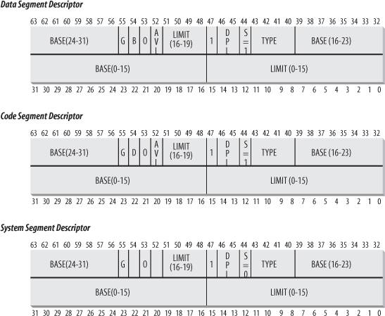
Local Descriptor Table Descriptor (LDTD) Indicates that the Segment Descriptor refers to a segment containing an LDT; it can appear only in the GDT. The corresponding Type field has the value 2. The S flag of such descriptors is set to 0. The next section shows how 80 x 86 processors are able to decide whether a segment descriptor is stored in the GDT or in the LDT of the process.
2.2.3. Fast Access to Segment Descriptors
We recall that logical addresses consist of a 16-bit Segment Selector and a 32-bit Offset, and that segmentation registers store only the Segment Selector.
To speed up the translation of logical addresses into linear addresses, the 80 x 86 processor provides an additional nonprogrammable registerthat is, a register that cannot be set by a programmerfor each of the six programmable segmentation registers. Each nonprogrammable register contains the 8-byte Segment Descriptor (described in the previous section) specified by the Segment Selector contained in the corresponding segmentation register. Every time a Segment Selector is loaded in a segmentation register, the corresponding Segment Descriptor is loaded from memory into the matching nonprogrammable CPU register. From then on, translations of logical addresses referring to that segment can be performed without accessing the GDT or LDT stored in main memory; the processor can refer only directly to the CPU register containing the Segment Descriptor. Accesses to the GDT or LDT are necessary only when the contents of the segmentation registers change (see Figure 2-4).
Any Segment Selector includes three fields that are described in Table 2-2.
Table 2-2. Segment Selector fieldsField name | Description |
|---|
index | Identifies the Segment Descriptor entry contained in the GDT or in the LDT (described further in the text following this table). | TI | Table Indicator
: specifies whether the Segment Descriptor is included in the GDT (TI = 0) or in the LDT (TI = 1). | RPL | Requestor Privilege Level
: specifies the Current Privilege Level of the CPU when the corresponding Segment Selector is loaded into the cs register; it also may be used to selectively weaken the processor privilege level when accessing data segments (see Intel documentation for details). |
Because a Segment Descriptor is 8 bytes long, its relative address inside the GDT or the LDT is obtained by multiplying the 13-bit index field of the Segment Selector by 8. For instance, if the GDT is at 0x00020000 (the value stored in the gdtr register) and the index specified by the Segment Selector is 2, the address of the corresponding Segment Descriptor is 0x00020000 + (2 x 8), or 0x00020010.
The first entry of the GDT is always set to 0. This ensures that logical addresses with a null Segment Selector will be considered invalid, thus causing a processor exception. The maximum number of Segment Descriptors that can be stored in the GDT is 8,191 (i.e., 213-1).
2.2.4. Segmentation Unit
Figure 2-5 shows in detail how a logical address is translated into a corresponding linear address. The segmentation unit performs the following operations:
Examines the TI field of the Segment Selector to determine which Descriptor Table stores the Segment Descriptor. This field indicates that the Descriptor is either in the GDT (in which case the segmentation unit gets the base linear address of the GDT from the gdtr register) or in the active LDT (in which case the segmentation unit gets the base linear address of that LDT from the ldtr
register). Computes the address of the Segment Descriptor from the index field of the Segment Selector. The index field is multiplied by 8 (the size of a Segment Descriptor), and the result is added to the content of the gdtr or ldtr register. Adds the offset of the logical address to the Base field of the Segment Descriptor, thus obtaining the linear address.
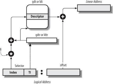
Notice that, thanks to the nonprogrammable registers associated with the segmentation registers, the first two operations need to be performed only when a segmentation register has been changed.
2.3. Segmentation in Linux
Segmentation has been included in 80 x 86 microprocessors to encourage programmers to split their applications into logically related entities, such as subroutines or global and local data areas. However, Linux uses segmentation in a very limited way. In fact, segmentation and paging are somewhat redundant, because both can be used to separate the physical address spaces of processes: segmentation can assign a different linear address space to each process, while paging can map the same linear address space into different physical address spaces. Linux prefers paging to segmentation for the following reasons:
Memory management is simpler when all processes use the same segment register values that is, when they share the same set of linear addresses. One of the design objectives of Linux is portability to a wide range of architectures; RISC architectures in particular have limited support for segmentation.
The 2.6 version of Linux uses segmentation only when required by the 80 x 86 architecture.
All Linux processes running in User Mode use the same pair of segments to address instructions and data. These segments are called user code segment
and user data segment
, respectively. Similarly, all Linux processes running in Kernel Mode use the same pair of segments to address instructions and data: they are called kernel code segment
and kernel data segment
, respectively. Table 2-3 shows the values of the Segment Descriptor fields for these four crucial segments.
Table 2-3. Values of the Segment Descriptor fields for the four main Linux segmentsSegment | Base | G | Limit | S | Type | DPL | D/B | P |
|---|
user code | 0x00000000 | 1 | 0xfffff | 1 | 10 | 3 | 1 | 1 | user data | 0x00000000 | 1 | 0xfffff | 1 | 2 | 3 | 1 | 1 | kernel code | 0x00000000 | 1 | 0xfffff | 1 | 10 | 0 | 1 | 1 | kernel data | 0x00000000 | 1 | 0xfffff | 1 | 2 | 0 | 1 | 1 |
The corresponding Segment Selectors are defined by the macros _ _USER_CS, _ _USER_DS, _ _KERNEL_CS, and _ _KERNEL_DS, respectively. To address the kernel code segment, for instance, the kernel just loads the value yielded by the _ _KERNEL_CS macro into the cs segmentation register.
Notice that the linear addresses associated with such segments all start at 0 and reach the addressing limit of 232 -1. This means that all processes, either in User Mode or in Kernel Mode, may use the same logical addresses.
Another important consequence of having all segments start at 0x00000000 is that in Linux, logical addresses coincide with linear addresses; that is, the value of the Offset field of a logical address always coincides with the value of the corresponding linear address.
As stated earlier, the Current Privilege Level of the CPU indicates whether the processor is in User or Kernel Mode and is specified by the RPL field of the Segment Selector stored in the cs register. Whenever the CPL is changed, some segmentation registers must be correspondingly updated. For instance, when the CPL is equal to 3 (User Mode), the ds register must contain the Segment Selector of the user data segment, but when the CPL is equal to 0, the ds register must contain the Segment Selector of the kernel data segment.
A similar situation occurs for the ss register. It must refer to a User Mode stack inside the user data segment when the CPL is 3, and it must refer to a Kernel Mode stack inside the kernel data segment when the CPL is 0. When switching from User Mode to Kernel Mode, Linux always makes sure that the ss register contains the Segment Selector of the kernel data segment.
When saving a pointer to an instruction or to a data structure, the kernel does not need to store the Segment Selector component of the logical address, because the ss register contains the current Segment Selector. As an example, when the kernel invokes a function, it executes a call
assembly language instruction specifying just the Offset component of its logical address; the Segment Selector is implicitly selected as the one referred to by the cs register. Because there is just one segment of type "executable in Kernel Mode," namely the code segment identified by __KERNEL_CS, it is sufficient to load __KERNEL_CS into cs whenever the CPU switches to Kernel Mode. The same argument goes for pointers to kernel data structures (implicitly using the ds register), as well as for pointers to user data structures (the kernel explicitly uses the es register).
Besides the four segments just described, Linux makes use of a few other specialized segments. We'll introduce them in the next section while describing the Linux GDT.
2.3.1. The Linux GDT
In uniprocessor systems there is only one GDT, while in multiprocessor systems there is one GDT for every CPU in the system. All GDTs are stored in the cpu_gdt_table array, while the addresses and sizes of the GDTs (used when initializing the gdtr registers) are stored in the cpu_gdt_descr array. If you look in the Source Code Index, you can see that these symbols are defined in the file arch/i386/kernel/head.S
. Every macro, function, and other symbol in this book is listed in the Source Code Index, so you can quickly find it in the source code.
The layout of the GDTs is shown schematically in Figure 2-6. Each GDT includes 18 segment descriptors and 14 null, unused, or reserved entries. Unused entries are inserted on purpose so that Segment Descriptors usually accessed together are kept in the same 32-byte line of the hardware cache (see the section "Hardware Cache" later in this chapter).
The 18 segment descriptors included in each GDT point to the following segments:
Four user and kernel code and data segments (see previous section). A Task State Segment (TSS), different for each processor in the system. The linear address space corresponding to a TSS is a small subset of the linear address space corresponding to the kernel data segment. The Task State Segments are sequentially stored in the init_tss array; in particular, the Base field of the TSS descriptor for the nth CPU points to the nth component of the init_tss array. The G (granularity) flag is cleared, while the Limit field is set to 0xeb, because the TSS segment is 236 bytes long. The Type field is set to 9 or 11 (available 32-bit TSS), and the DPL is set to 0, because processes in User Mode are not allowed to access TSS segments. You will find details on how Linux uses TSSs in the section "Task State Segment" in Chapter 3.
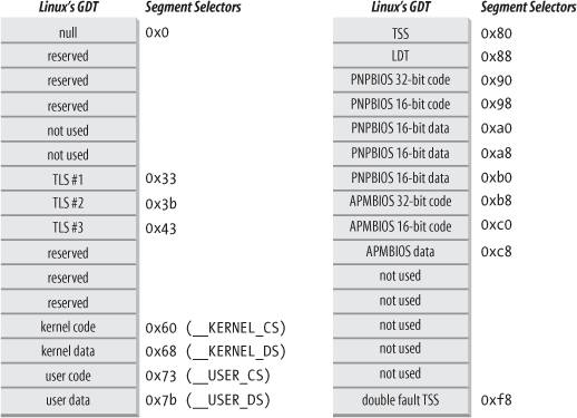 A segment including the default Local Descriptor Table (LDT), usually shared by all processes (see the next section). Three Thread-Local Storage (TLS) segments: this is a mechanism that allows multithreaded applications to make use of up to three segments containing data local to each thread. The set_thread_area( )
and get_thread_area( )
system calls, respectively, create and release a TLS segment for the executing process. Three segments related to Advanced Power Management (APM
): the BIOS
code makes use of segments, so when the Linux APM driver invokes BIOS functions to get or set the status of APM devices, it may use custom code and data segments. Five segments related to Plug and Play (PnP
) BIOS services. As in the previous case, the BIOS code makes use of segments, so when the Linux PnP driver invokes BIOS functions to detect the resources used by PnP devices, it may use custom code and data segments. A special TSS segment used by the kernel to handle "Double fault
" exceptions (see "Exceptions" in Chapter 4).
As stated earlier, there is a copy of the GDT for each processor in the system. All copies of the GDT store identical entries, except for a few cases. First, each processor has its own TSS segment, thus the corresponding GDT's entries differ. Moreover, a few entries in the GDT may depend on the process that the CPU is executing (LDT and TLS Segment Descriptors). Finally, in some cases a processor may temporarily modify an entry in its copy of the GDT; this happens, for instance, when invoking an APM's BIOS procedure.
2.3.2. The Linux LDTs
Most Linux User Mode applications do not make use of a Local Descriptor Table, thus the kernel defines a default LDT to be shared by most processes. The default Local Descriptor Table is stored in the default_ldt array. It includes five entries, but only two of them are effectively used by the kernel: a call gate for iBCS executables, and a call gate for Solaris
/x86 executables (see the section "Execution Domains" in Chapter 20). Call gates are a mechanism provided by 80 x 86 microprocessors to change the privilege level of the CPU while invoking a predefined function; as we won't discuss them further, you should consult the Intel documentation for more details.
In some cases, however, processes may require to set up their own LDT. This turns out to be useful to applications (such as Wine) that execute segment-oriented Microsoft Windows
applications. The modify_ldt( )
system call allows a process to do this.
Any custom LDT created by modify_ldt( ) also requires its own segment. When a processor starts executing a process having a custom LDT, the LDT entry in the CPU-specific copy of the GDT is changed accordingly.
User Mode applications also may allocate new segments by means of modify_ldt( ); the kernel, however, never makes use of these segments, and it does not have to keep track of the corresponding Segment Descriptors, because they are included in the custom LDT of the process.
2.4. Paging in Hardware
The paging unit translates linear addresses into physical ones. One key task in the unit is to check the requested access type against the access rights of the linear address. If the memory access is not valid, it generates a Page Fault
exception (see Chapter 4 and Chapter 8).
For the sake of efficiency, linear addresses are grouped in fixed-length intervals called pages
; contiguous linear addresses within a page are mapped into contiguous physical addresses. In this way, the kernel can specify the physical address and the access rights of a page instead of those of all the linear addresses included in it. Following the usual convention, we shall use the term "page" to refer both to a set of linear addresses and to the data contained in this group of addresses.
The paging
unit thinks of all RAM as partitioned into fixed-length page frames
(sometimes referred to as physical pages
). Each page frame contains a page that is, the length of a page frame coincides with that of a page. A page frame is a constituent of main memory, and hence it is a storage area. It is important to distinguish a page from a page frame; the former is just a block of data, which may be stored in any page frame or on disk.
The data structures that map linear to physical addresses are called page tables
; they are stored in main memory and must be properly initialized by the kernel before enabling the paging unit.
Starting with the 80386, all 80 x 86 processors support paging; it is enabled by setting the PG flag of a control register named cr0
. When PG = 0, linear addresses are interpreted as physical addresses.
2.4.1. Regular Paging
Starting with the 80386, the paging unit of Intel processors handles 4 KB pages.
The 32 bits of a linear address are divided into three fields:
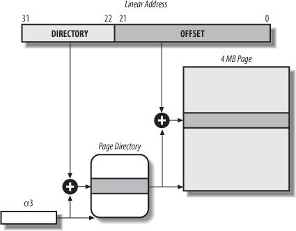
Directory The most significant 10 bits
Table The intermediate 10 bits
Offset The least significant 12 bits
The translation of linear addresses is accomplished in two steps, each based on a type of translation table. The first translation table is called the Page Directory, and the second is called the Page Table.
The aim of this two-level
scheme is to reduce the amount of RAM required for per-process Page Tables. If a simple one-level Page Table was used, then it would require up to 220 entries (i.e., at 4 bytes per entry, 4 MB of RAM) to represent the Page Table for each process (if the process used a full 4 GB linear address space), even though a process does not use all addresses in that range. The two-level scheme reduces the memory by requiring Page Tables only for those virtual memory regions actually used by a process.
Each active process must have a Page Directory assigned to it. However, there is no need to allocate RAM for all Page Tables of a process at once; it is more efficient to allocate RAM for a Page Table only when the process effectively needs it.
The physical address of the Page Directory in use is stored in a control register named cr3
. The Directory field within the linear address determines the entry in the Page Directory that points to the proper Page Table. The address's Table field, in turn, determines the entry in the Page Table that contains the physical address of the page frame containing the page. The Offset field determines the relative position within the page frame (see Figure 2-7). Because it is 12 bits long, each page consists of 4096 bytes of data.
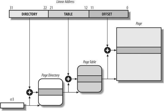
Both the Directory and the Table fields are 10 bits long, so Page Directories and Page Tables can include up to 1,024 entries. It follows that a Page Directory can address up to 1024 x 1024 x 4096=232 memory cells, as you'd expect in 32-bit addresses.
The entries of Page Directories and Page Tables have the same structure. Each entry includes the following fields:
Present flag If it is set, the referred-to page (or Page Table) is contained in main memory; if the flag is 0, the page is not contained in main memory and the remaining entry bits may be used by the operating system for its own purposes. If the entry of a Page Table or Page Directory needed to perform an address translation has the Present flag cleared, the paging unit stores the linear address in a control register named cr2
and generates exception 14: the Page Fault
exception. (We will see in Chapter 17 how Linux uses this field.)
Field containing the 20 most significant bits of a page frame physical address Because each page frame has a 4-KB capacity, its physical address must be a multiple of 4096, so the 12 least significant bits of the physical address are always equal to 0. If the field refers to a Page Directory, the page frame contains a Page Table; if it refers to a Page Table, the page frame contains a page of data.
Accessed flag Set each time the paging unit addresses the corresponding page frame. This flag may be used by the operating system when selecting pages to be swapped out. The paging unit never resets this flag; this must be done by the operating system.
Dirty flag Applies only to the Page Table entries. It is set each time a write operation is performed on the page frame. As with the Accessed flag, Dirty may be used by the operating system when selecting pages to be swapped out. The paging unit never resets this flag; this must be done by the operating system.
Read/Write flag Contains the access right (Read/Write or Read) of the page or of the Page Table (see the section "Hardware Protection Scheme" later in this chapter).
User/Supervisor flag Contains the privilege level required to access the page or Page Table (see the later section "Hardware Protection Scheme").
PCD and PWT flags Controls the way the page or Page Table is handled by the hardware cache (see the section "Hardware Cache" later in this chapter).
Page Size flag Applies only to Page Directory entries. If it is set, the entry refers to a 2 MB- or 4 MB-long page frame (see the following sections).
Global flag Applies only to Page Table entries. This flag was introduced in the Pentium Pro to prevent frequently used pages from being flushed from the TLB cache (see the section "Translation Lookaside Buffers (TLB)" later in this chapter). It works only if the Page Global Enable (PGE) flag of register cr4
is set.
2.4.2. Extended Paging
Starting with the Pentium model, 80 x 86 microprocessors introduce extended paging
, which allows page frames to be 4 MB instead of 4 KB in size (see Figure 2-8). Extended paging is used to translate large contiguous linear address ranges into corresponding physical ones; in these cases, the kernel can do without intermediate Page Tables and thus save memory and preserve TLB entries (see the section "Translation Lookaside Buffers (TLB)").
As mentioned in the previous section, extended paging is enabled by setting the Page Size flag of a Page Directory entry. In this case, the paging unit divides the 32 bits of a linear address into two fields:
Directory The most significant 10 bits
Offset The remaining 22 bits
Page Directory entries for extended paging are the same as for normal paging, except that:
The Page Size flag must be set. Only the 10 most significant bits of the 20-bit physical address field are significant. This is because each physical address is aligned on a 4-MB boundary, so the 22 least significant bits of the address are 0.
Extended paging coexists with regular paging; it is enabled by setting the PSE flag of the cr4 processor register.
2.4.3. Hardware Protection Scheme
The paging unit uses a different protection scheme from the segmentation unit. While 80 x 86 processors allow four possible privilege levels to a segment, only two privilege levels are associated with pages and Page Tables, because privileges are controlled by the User/Supervisor flag mentioned in the earlier section "Regular Paging." When this flag is 0, the page can be addressed only when the CPL is less than 3 (this means, for Linux, when the processor is in Kernel Mode). When the flag is 1, the page can always be addressed.
Furthermore, instead of the three types of access rights (Read, Write, and Execute) associated with segments, only two types of access rights (Read and Write) are associated with pages. If the Read/Write flag of a Page Directory or Page Table entry is equal to 0, the corresponding Page Table or page can only be read; otherwise it can be read and written.
2.4.4. An Example of Regular Paging
A simple example will help in clarifying how regular paging works. Let's assume that the kernel assigns the linear address space between 0x20000000 and 0x2003ffff to a running process. This space consists of exactly 64 pages. We don't care about the physical addresses of the page frames containing the pages; in fact, some of them might not even be in main memory. We are interested only in the remaining fields of the Page Table entries.
Let's start with the 10 most significant bits of the linear addresses assigned to the process, which are interpreted as the Directory field by the paging unit. The addresses start with a 2 followed by zeros, so the 10 bits all have the same value, namely 0x080 or 128 decimal. Thus the Directory field in all the addresses refers to the 129th entry of the process Page Directory. The corresponding entry must contain the physical address of the Page Table assigned to the process (see Figure 2-9). If no other linear addresses are assigned to the process, all the remaining 1,023 entries of the Page Directory are filled with zeros.
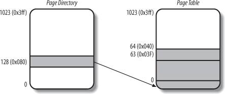
The values assumed by the intermediate 10 bits, (that is, the values of the Table field) range from 0 to 0x03f, or from 0 to 63 decimal. Thus, only the first 64 entries of the Page Table are valid. The remaining 960 entries are filled with zeros.
Suppose that the process needs to read the byte at linear address 0x20021406. This address is handled by the paging unit as follows:
The Directory field 0x80 is used to select entry 0x80 of the Page Directory, which points to the Page Table associated with the process's pages. The Table field 0x21 is used to select entry 0x21 of the Page Table, which points to the page frame containing the desired page. Finally, the Offset field 0x406 is used to select the byte at offset 0x406 in the desired page frame.
If the Present flag of the 0x21 entry of the Page Table is cleared, the page is not present in main memory; in this case, the paging unit issues a Page Fault
exception while translating the linear address. The same exception is issued whenever the process attempts to access linear addresses outside of the interval delimited by 0x20000000 and 0x2003ffff, because the Page Table entries not assigned to the process are filled with zeros; in particular, their Present flags are all cleared.
2.4.5. The Physical Address Extension (PAE) Paging Mechanism
The amount of RAM supported by a processor is limited by the number of address pins connected to the address bus. Older Intel processors from the 80386 to the Pentium used 32-bit physical addresses. In theory, up to 4 GB of RAM could be installed on such systems; in practice, due to the linear address space requirements of User Mode processes, the kernel cannot directly address more than 1 GB of RAM, as we will see in the later section "Paging in Linux."
However, big servers that need to run hundreds or thousands of processes at the same time require more than 4 GB of RAM, and in recent years this created a pressure on Intel to expand the amount of RAM supported on the 32-bit 80 x 86 architecture.
Intel has satisfied these requests by increasing the number of address pins on its processors from 32 to 36. Starting with the Pentium Pro, all Intel processors are now able to address up to 236 = 64 GB of RAM. However, the increased range of physical addresses can be exploited only by introducing a new paging mechanism that translates 32-bit linear addresses into 36-bit physical ones.
With the Pentium Pro processor, Intel introduced a mechanism called Physical Address Extension (PAE). Another mechanism, Page Size Extension (PSE-36), was introduced in the Pentium III processor, but Linux does not use it, and we won't discuss it further in this book.
PAE is activated by setting the Physical Address Extension (PAE) flag in the cr4 control register. The Page Size (PS) flag in the page directory entry enables large page sizes (2 MB when PAE is enabled).
Intel has changed the paging mechanism in order to support PAE.
The 64 GB of RAM are split into 224 distinct page frames, and the physical address field of Page Table entries has been expanded from 20 to 24 bits. Because a PAE Page Table entry must include the 12 flag bits (described in the earlier section "Regular Paging") and the 24 physical address bits, for a grand total of 36, the Page Table entry size has been doubled from 32 bits to 64 bits. As a result, a 4-KB PAE Page Table includes 512 entries instead of 1,024. A new level of Page Table called the Page Directory Pointer Table (PDPT) consisting of four 64-bit entries has been introduced. The cr3
control register contains a 27-bit Page Directory Pointer Table base address field. Because PDPTs are stored in the first 4 GB of RAM and aligned to a multiple of 32 bytes (25), 27 bits are sufficient to represent the base address of such tables. When mapping linear addresses to 4 KB pages (PS flag cleared in Page Directory entry), the 32 bits of a linear address are interpreted in the following way:
cr3 Points to a PDPT
bits 3130 Point to 1 of 4 possible entries in PDPT
bits 2921 Point to 1 of 512 possible entries in Page Directory
bits 2012 Point to 1 of 512 possible entries in Page Table
bits 11-0 Offset of 4-KB page
When mapping linear addresses to 2-MB pages (PS flag set in Page Directory entry), the 32 bits of a linear address are interpreted in the following way:
cr3 Points to a PDPT
bits 31-30 Point to 1 of 4 possible entries in PDPT
bits 2921 Point to 1 of 512 possible entries in Page Directory
bits 20-0 Offset of 2-MB page
To summarize, once cr3 is set, it is possible to address up to 4 GB of RAM. If we want to address more RAM, we'll have to put a new value in cr3 or change the content of the PDPT. However, the main problem with PAE is that linear addresses are still 32 bits long. This forces kernel programmers to reuse the same linear addresses to map different areas of RAM. We'll sketch how Linux initializes Page Tables when PAE is enabled in the later section, "Final kernel Page Table when RAM size is more than 4096 MB." Clearly, PAE does not enlarge the linear address space of a process, because it deals only with physical addresses. Furthermore, only the kernel can modify the page tables of the processes, thus a process running in User Mode cannot use a physical address space larger than 4 GB. On the other hand, PAE allows the kernel to exploit up to 64 GB of RAM, and thus to increase significantly the number of processes in the system.
2.4.6. Paging for 64-bit Architectures
As we have seen in the previous sections, two-level
paging is commonly used by 32-bit microprocessors. Two-level paging, however, is not suitable for computers that adopt a 64-bit architecture. Let's use a thought experiment to explain why:
Start by assuming a standard page size of 4 KB. Because 1 KB covers a range of 210 addresses, 4 KB covers 212 addresses, so the Offset field is 12 bits. This leaves up to 52 bits of the linear address to be distributed between the Table and the Directory fields. If we now decide to use only 48 of the 64 bits for addressing (this restriction leaves us with a comfortable 256 TB address space!), the remaining 48-12 = 36 bits will have to be split among Table and the Directory fields. If we now decide to reserve 18 bits for each of these two fields, both the Page Directory and the Page Tables of each process should include 218 entries that is, more than 256,000 entries.
For that reason, all hardware paging systems for 64-bit processors make use of additional paging levels. The number of levels used depends on the type of processor. Table 2-4 summarizes the main characteristics of the hardware paging systems used by some 64-bit platforms supported by Linux. Please refer to the section "Hardware Dependency" in Chapter 1 for a short description of the hardware associated with the platform name.
Table 2-4. Paging levels in some 64-bit architecturesPlatform name | Page size | Number of address bits used | Number of paging levels | Linear address splitting |
|---|
alpha | 8 KB a | 43 | 3 | 10 + 10 + 10 + 13 | ia64 | 4 KB a | 39 | 3 | 9 + 9 + 9 + 12 | ppc64 | 4 KB | 41 | 3 | 10 + 10 + 9 + 12 | sh64 | 4 KB | 41 | 3 | 10 + 10 + 9 + 12 | x86_64 | 4 KB | 48 | 4 | 9 + 9 + 9 + 9 + 12 | |
As we will see in the section "Paging in Linux" later in this chapter, Linux succeeds in providing a common paging model that fits most of the supported hardware paging systems.
2.4.7. Hardware Cache
Today's microprocessors have clock rates of several gigahertz, while dynamic RAM (DRAM) chips have access times in the range of hundreds of clock cycles. This means that the CPU may be held back considerably while executing instructions that require fetching operands from RAM and/or storing results into RAM.
Hardware cache memories were introduced to reduce the speed mismatch between CPU and RAM. They are based on the well-known locality principle
, which holds both for programs and data structures. This states that because of the cyclic structure of programs and the packing of related data into linear arrays, addresses close to the ones most recently used have a high probability of being used in the near future. It therefore makes sense to introduce a smaller and faster memory that contains the most recently used code and data. For this purpose, a new unit called the line was introduced into the 80 x 86 architecture. It consists of a few dozen contiguous bytes that are transferred in burst mode between the slow DRAM and the fast on-chip static RAM (SRAM) used to implement caches.
The cache is subdivided into subsets of lines
. At one extreme, the cache can be direct mapped
, in which case a line in main memory is always stored at the exact same location in the cache. At the other extreme, the cache is fully associative
, meaning that any line in memory can be stored at any location in the cache. But most caches are to some degree N-way set associative
, where any line of main memory can be stored in any one of N lines of the cache. For instance, a line of memory can be stored in two different lines of a two-way set associative cache.
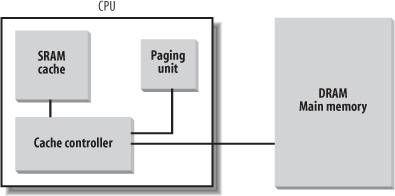
As shown in Figure 2-10, the cache unit is inserted between the paging unit and the main memory. It includes both a hardware cache memory and a cache controller. The cache memory stores the actual lines of memory. The cache controller stores an array of entries, one entry for each line of the cache memory. Each entry includes a tag and a few flags that describe the status of the cache line. The tag consists of some bits that allow the cache controller to recognize the memory location currently mapped by the line. The bits of the memory's physical address are usually split into three groups: the most significant ones correspond to the tag, the middle ones to the cache controller subset index, and the least significant ones to the offset within the line.
When accessing a RAM memory cell, the CPU extracts the subset index from the physical address and compares the tags of all lines in the subset with the high-order bits of the physical address. If a line with the same tag as the high-order bits of the address is found, the CPU has a cache hit; otherwise, it has a cache miss.
When a cache hit occurs, the cache controller behaves differently, depending on the access type. For a read operation, the controller selects the data from the cache line and transfers it into a CPU register; the RAM is not accessed and the CPU saves time, which is why the cache system was invented. For a write operation, the controller may implement one of two basic strategies called write-through
and write-back
. In a write-through, the controller always writes into both RAM and the cache line, effectively switching off the cache for write operations. In a write-back, which offers more immediate efficiency, only the cache line is updated and the contents of the RAM are left unchanged. After a write-back, of course, the RAM must eventually be updated. The cache controller writes the cache line back into RAM only when the CPU executes an instruction requiring a flush of cache entries or when a FLUSH hardware signal occurs (usually after a cache miss).
When a cache miss occurs, the cache line is written to memory, if necessary, and the correct line is fetched from RAM into the cache entry.
Multiprocessor systems have a separate hardware cache for every processor, and therefore they need additional hardware circuitry to synchronize the cache contents. As shown in Figure 2-11, each CPU has its own local hardware cache. But now updating becomes more time consuming: whenever a CPU modifies its hardware cache, it must check whether the same data is contained in the other hardware cache; if so, it must notify the other CPU to update it with the proper value. This activity is often called cache snooping
. Luckily, all this is done at the hardware level and is of no concern to the kernel.
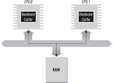
Cache technology is rapidly evolving. For example, the first Pentium models included a single on-chip cache called the L1-cache. More recent models also include other larger, slower on-chip caches called the L2-cache, L3-cache, etc. The consistency between the cache levels is implemented at the hardware level. Linux ignores these hardware details and assumes there is a single cache.
The CD flag of the cr0
processor register is used to enable or disable the cache circuitry. The NW flag, in the same register, specifies whether the write-through or the write-back strategy is used for the caches.
Another interesting feature of the Pentium cache is that it lets an operating system associate a different cache management policy with each page frame. For this purpose, each Page Directory and each Page Table entry includes two flags: PCD (Page Cache Disable), which specifies whether the cache must be enabled or disabled while accessing data included in the page frame; and PWT (Page Write-Through), which specifies whether the write-back or the write-through strategy must be applied while writing data into the page frame. Linux clears the PCD and PWT flags of all Page Directory and Page Table entries; as a result, caching is enabled for all page frames, and the write-back strategy is always adopted for writing.
2.4.8. Translation Lookaside Buffers (TLB)
Besides general-purpose hardware caches, 80 x 86 processors include another cache called Translation Lookaside Buffers (TLB) to speed up linear address translation. When a linear address is used for the first time, the corresponding physical address is computed through slow accesses to the Page Tables in RAM. The physical address is then stored in a TLB entry so that further references to the same linear address can be quickly translated.
In a multiprocessor system, each CPU has its own TLB, called the local TLB of the CPU. Contrary to the hardware cache, the corresponding entries of the TLB need not be synchronized, because processes running on the existing CPUs may associate the same linear address with different physical ones.
When the cr3
control register of a CPU is modified, the hardware automatically invalidates all entries of the local TLB, because a new set of page tables is in use and the TLBs
are pointing to old data.
2.5. Paging in Linux
Linux adopts a common paging model that fits both 32-bit and 64-bit architectures. As explained in the earlier section "Paging for 64-bit Architectures," two paging levels are sufficient for 32-bit architectures, while 64-bit architectures require a higher number of paging levels. Up to version 2.6.10, the Linux paging model consisted of three paging levels. Starting with version 2.6.11, a four-level
paging model has been adopted. The four types of page tables illustrated in Figure 2-12 are called:
Page Global Directory Page Upper Directory Page Middle Directory Page Table
The Page Global Directory includes the addresses of several Page Upper Directories, which in turn include the addresses of several Page Middle Directories, which in turn include the addresses of several Page Tables. Each Page Table entry points to a page frame. Thus the linear address can be split into up to five parts. Figure 2-12 does not show the bit numbers, because the size of each part depends on the computer architecture.
For 32-bit architectures with no Physical Address Extension, two paging levels are sufficient. Linux essentially eliminates the Page Upper Directory and the Page Middle Directory fields by saying that they contain zero bits. However, the positions of the Page Upper Directory and the Page Middle Directory in the sequence of pointers are kept so that the same code can work on 32-bit and 64-bit architectures. The kernel keeps a position for the Page Upper Directory and the Page Middle Directory by setting the number of entries in them to 1 and mapping these two entries into the proper entry of the Page Global Directory.
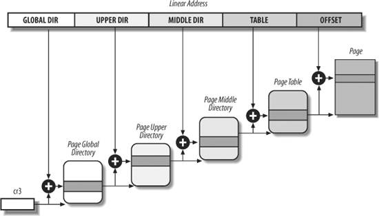
For 32-bit architectures with the Physical Address Extension enabled, three paging levels are used. The Linux's Page Global Directory corresponds to the 80 x 86's Page Directory Pointer Table, the Page Upper Directory is eliminated, the Page Middle Directory corresponds to the 80 x 86's Page Directory, and the Linux's Page Table corresponds to the 80 x 86's Page Table.
Finally, for 64-bit architectures three or four levels of paging are used depending on the linear address bit splitting performed by the hardware (see Table 2-2).
Linux's handling of processes relies heavily on paging. In fact, the automatic translation of linear addresses into physical ones makes the following design objectives feasible:
Assign a different physical address space to each process, ensuring an efficient protection against addressing errors. Distinguish pages (groups of data) from page frames (physical addresses in main memory). This allows the same page to be stored in a page frame, then saved to disk and later reloaded in a different page frame. This is the basic ingredient of the virtual memory mechanism (see Chapter 17).
In the remaining part of this chapter, we will refer for the sake of concreteness to the paging circuitry used by the 80 x 86 processors.
As we will see in Chapter 9, each process has its own Page Global Directory and its own set of Page Tables. When a process switch occurs (see the section "Process Switch" in Chapter 3), Linux saves the cr3
control register in the descriptor of the process previously in execution and then loads cr3 with the value stored in the descriptor of the process to be executed next. Thus, when the new process resumes its execution on the CPU, the paging unit refers to the correct set of Page Tables.
Mapping linear to physical addresses now becomes a mechanical task, although it is still somewhat complex. The next few sections of this chapter are a rather tedious list of functions and macros that retrieve information the kernel needs to find addresses and manage the tables; most of the functions are one or two lines long. You may want to only skim these sections now, but it is useful to know the role of these functions and macros, because you'll see them often in discussions throughout this book.
2.5.1. The Linear Address Fields
The following macros simplify Page Table handling:
PAGE_SHIFT Specifies the length in bits of the Offset field; when applied to 80 x 86 processors, it yields the value 12. Because all the addresses in a page must fit in the Offset field, the size of a page on 80 x 86 systems is 212 or the familiar 4,096 bytes; the PAGE_SHIFT of 12 can thus be considered the logarithm base 2 of the total page size. This macro is used by PAGE_SIZE to return the size of the page. Finally, the PAGE_MASK macro yields the value 0xfffff000 and is used to mask all the bits of the Offset field.
PMD_SHIFT The total length in bits of the Offset and Table fields of a linear address; in other words, the logarithm of the size of the area a Page Middle Directory entry can map. The PMD_SIZE macro computes the size of the area mapped by a single entry of the Page Middle Directory that is, of a Page Table. The PMD_MASK macro is used to mask all the bits of the Offset and Table fields.
When PAE is disabled, PMD_SHIFT yields the value 22 (12 from Offset plus 10 from Table), PMD_SIZE yields 222 or 4 MB, and PMD_MASK yields 0xffc00000. Conversely, when PAE is enabled, PMD_SHIFT yields the value 21 (12 from Offset plus 9 from Table), PMD_SIZE yields 221 or 2 MB, and PMD_MASK yields 0xffe00000.
Large pages do not make use of the last level of page tables, thus LARGE_PAGE_SIZE, which yields the size of a large page, is equal to PMD_SIZE (2PMD_SHIFT) while LARGE_PAGE_MASK, which is used to mask all the bits of the Offset and Table fields in a large page address, is equal to PMD_MASK.
PUD_SHIFT Determines the logarithm of the size of the area a Page Upper Directory entry can map. The PUD_SIZE macro computes the size of the area mapped by a single entry of the Page Global Directory. The PUD_MASK macro is used to mask all the bits of the Offset, Table, Middle Air, and Upper Air fields.
On the 80 x 86 processors, PUD_SHIFT is always equal to PMD_SHIFT and PUD_SIZE is equal to 4 MB or 2 MB.
PGDIR_SHIFT Determines the logarithm of the size of the area that a Page Global Directory entry can map. The PGDIR_SIZE macro computes the size of the area mapped by a single entry of the Page Global Directory. The PGDIR_MASK macro is used to mask all the bits of the Offset, Table, Middle Air, and Upper Air fields.
When PAE is disabled, PGDIR_SHIFT yields the value 22 (the same value yielded by PMD_SHIFT and by PUD_SHIFT), PGDIR_SIZE yields 222 or 4 MB, and PGDIR_MASK yields 0xffc00000. Conversely, when PAE is enabled, PGDIR_SHIFT yields the value 30 (12 from Offset plus 9 from Table plus 9 from Middle Air), PGDIR_SIZE yields 230 or 1 GB, and PGDIR_MASK yields 0xc0000000.
PTRS_PER_PTE, PTRS_PER_PMD, PTRS_PER_PUD, and PTRS_PER_PGD Compute the number of entries in the Page Table, Page Middle Directory, Page Upper Directory, and Page Global Directory. They yield the values 1,024, 1, 1, and 1,024, respectively, when PAE is disabled; and the values 512, 512, 1, and 4, respectively, when PAE is enabled.
2.5.2. Page Table Handling
pte_t, pmd_t, pud_t, and pgd_t describe the format of, respectively, a Page Table, a Page Middle Directory, a Page Upper Directory, and a Page Global Directory entry. They are 64-bit data types when PAE is enabled and 32-bit data types otherwise. pgprot_t is another 64-bit (PAE enabled) or 32-bit (PAE disabled) data type that represents the protection flags associated with a single entry.
Five type-conversion macros _ _ pte, _ _ pmd, _ _ pud, _ _ pgd, and _ _ pgprot cast an unsigned integer into the required type. Five other type-conversion macros pte_val, pmd_val, pud_val, pgd_val, and pgprot_val perform the reverse casting from one of the four previously mentioned specialized types into an unsigned integer.
The kernel also provides several macros and functions to read or modify page table entries:
pte_none, pmd_none, pud_none, and pgd_none yield the value 1 if the corresponding entry has the value 0; otherwise, they yield the value 0. pte_clear, pmd_clear, pud_clear, and pgd_clear clear an entry of the corresponding page table, thus forbidding a process to use the linear addresses mapped by the page table entry. The ptep_get_and_clear( ) function clears a Page Table entry and returns the previous value. set_pte, set_pmd, set_pud, and set_pgd write a given value into a page table entry; set_pte_atomic is identical to set_pte, but when PAE is enabled it also ensures that the 64-bit value is written atomically. pte_same(a,b) returns 1 if two Page Table entries a and b refer to the same page and specify the same access privileges, 0 otherwise. pmd_large(e) returns 1 if the Page Middle Directory entry e refers to a large page (2 MB or 4 MB), 0 otherwise.
The pmd_bad macro is used by functions to check Page Middle Directory entries passed as input parameters. It yields the value 1 if the entry points to a bad Page Table that is, if at least one of the following conditions applies:
The page is not in main memory (Present flag cleared). The page allows only Read access (Read/Write flag cleared). Either Accessed or Dirty is cleared (Linux always forces these flags to be set for every existing Page Table).
The pud_bad and pgd_bad macros always yield 0. No pte_bad macro is defined, because it is legal for a Page Table entry to refer to a page that is not present in main memory, not writable, or not accessible at all.
The pte_present macro yields the value 1 if either the Present flag or the Page Size flag of a Page Table entry is equal to 1, the value 0 otherwise. Recall that the Page Size flag in Page Table entries has no meaning for the paging unit of the microprocessor; the kernel, however, marks Present equal to 0 and Page Size equal to 1 for the pages present in main memory but without read, write, or execute privileges. In this way, any access to such pages triggers a Page Fault
exception because Present is cleared, and the kernel can detect that the fault is not due to a missing page by checking the value of Page Size.
The pmd_present macro yields the value 1 if the Present flag of the corresponding entry is equal to 1 that is, if the corresponding page or Page Table is loaded in main memory. The pud_present and pgd_present macros always yield the value 1.
The functions listed in Table 2-5 query the current value of any of the flags included in a Page Table entry; with the exception of pte_file(), these functions work properly only on Page Table entries for which pte_present returns 1.
Table 2-5. Page flag reading functionsFunction name | Description |
|---|
pte_user( ) | Reads the User/Supervisor flag | pte_read( ) | Reads the User/Supervisor flag (pages on the 80 x 86 processor cannot be protected against reading) | pte_write( ) | Reads the Read/Write flag | pte_exec( ) | Reads the User/Supervisor flag (pages on the 80 x 86 processor cannot be protected against code execution) | pte_dirty( ) | Reads the Dirty flag | pte_young( ) | Reads the Accessed flag | pte_file( ) | Reads the Dirty flag (when the Present flag is cleared and the Dirty flag is set, the page belongs to a non-linear disk file mapping; see Chapter 16) |
Another group of functions listed in Table 2-6 sets the value of the flags in a Page Table entry.
Table 2-6. Page flag setting functionsFunction name | Description |
|---|
mk_pte_huge( ) | Sets the Page Size and Present flags of a Page Table entry | pte_wrprotect( ) | Clears the Read/Write flag | pte_rdprotect( ) | Clears the User/Supervisor flag | pte_exprotect( ) | Clears the User/Supervisor flag | pte_mkwrite( ) | Sets the Read/Write flag | pte_mkread( ) | Sets the User/Supervisor flag | pte_mkexec( ) | Sets the User/Supervisor flag | pte_mkclean( ) | Clears the Dirty flag | pte_mkdirty( ) | Sets the Dirty flag | pte_mkold( ) | Clears the Accessed flag (makes the page old) | pte_mkyoung( ) | Sets the Accessed flag (makes the page young) | pte_modify(p,v) | Sets all access rights in a Page Table entry p to a specified value v | ptep_set_wrprotect( ) | Like pte_wrprotect( ), but acts on a pointer to a Page Table entry | ptep_set_access_flags() | If the Dirty flag is set, sets the page's access rights to a specified value and invokes flush_tlb_page() (see the section "Translation Lookaside Buffers (TLB)" later in this chapter) | ptep_mkdirty() | Like pte_mkdirty( ) but acts on a pointer to a Page Table entry | ptep_test_and_clear_dirty( ) | Like pte_mkclean( ) but acts on a pointer to a Page Table entry and returns the old value of the flag | ptep_test_and_clear_young( ) | Like pte_mkold( ) but acts on a pointer to a Page Table entry and returns the old value of the flag |
Now, let's discuss the macros listed in Table 2-7 that combine a page address and a group of protection flags into a page table entry or perform the reverse operation of extracting the page address from a page table entry. Notice that some of these macros refer to a page through the linear address of its "page descriptor" (see the section "Page Descriptors" in Chapter 8) rather than the linear address of the page itself.
Table 2-7. Macros acting on Page Table entriesMacro name | Description |
|---|
pgd_index(addr) | Yields the index (relative position) of the entry in the Page Global Directory that maps the linear address addr. | pgd_offset(mm, addr) | Receives as parameters the address of a memory descriptor cw (see Chapter 9) and a linear address addr. The macro yields the linear address of the entry in a Page Global Directory that corresponds to the address addr; the Page Global Directory is found through a pointer within the memory descriptor. | pgd_offset_k(addr) | Yields the linear address of the entry in the master kernel Page Global Directory
that corresponds to the address addr (see the later section "Kernel Page Tables"). | pgd_page(pgd) | Yields the page descriptor address of the page frame containing the Page Upper Directory referred to by the Page Global Directory entry pgd. In a two- or three-level paging system, this macro is equivalent to pud_page() applied to the folded Page Upper Directory entry. | pud_offset(pgd, addr) | Receives as parameters a pointer pgd to a Page Global Directory entry and a linear address addr. The macro yields the linear address of the entry in a Page Upper Directory that corresponds to addr. In a two- or three-level paging system, this macro yields pgd, the address of a Page Global Directory entry. | pud_page(pud) | Yields the linear address of the Page Middle Directory referred to by the Page Upper Directory entry pud. In a two-level paging system, this macro is equivalent to pmd_page() applied to the folded Page Middle Directory entry. | pmd_index(addr) | Yields the index (relative position) of the entry in the Page Middle Directory that maps the linear address addr. | pmd_offset(pud, addr) | Receives as parameters a pointer pud to a Page Upper Directory entry and a linear address addr. The macro yields the address of the entry in a Page Middle Directory that corresponds to addr. In a two-level paging system, it yields pud, the address of a Page Global Directory entry. | pmd_page(pmd) | Yields the page descriptor address of the Page Table referred to by the Page Middle Directory entry pmd. In a two-level paging system, pmd is actually an entry of a Page Global Directory. | mk_pte(p,prot) | Receives as parameters the address of a page descriptor p and a group of access rights prot, and builds the corresponding Page Table entry. | pte_index(addr) | Yields the index (relative position) of the entry in the Page Table that maps the linear address addr. | pte_offset_kernel(dir, addr) | Yields the linear address of the Page Table that corresponds to the linear address addr mapped by the Page Middle Directory dir. Used only on the master kernel page tables
(see the later section "Kernel Page Tables"). | pte_offset_map(dir, addr) | Receives as parameters a pointer dir to a Page Middle Directory entry and a linear address addr; it yields the linear address of the entry in the Page Table that corresponds to the linear address addr. If the Page Table is kept in high memory, the kernel establishes a temporary kernel mapping (see the section "Kernel Mappings of High-Memory Page Frames" in Chapter 8), to be released by means of pte_unmap. The macros pte_offset_map_nested and pte_unmap_nested are identical, but they use a different temporary kernel mapping. | pte_page(x) | Returns the page descriptor address of the page referenced by the Page Table entry x. | pte_to_pgoff(pte) | Extracts from the content pte of a Page Table entry the file offset corresponding to a page belonging to a non-linear file memory mapping (see the section "Non-Linear Memory Mappings" in Chapter 16). | pgoff_to_pte(offset ) | Sets up the content of a Page Table entry for a page belonging to a non-linear file memory mapping. |
The last group of functions of this long list was introduced to simplify the creation and deletion of page table entries.
When two-level
paging is used, creating or deleting a Page Middle Directory entry is trivial. As we explained earlier in this section, the Page Middle Directory contains a single entry that points to the subordinate Page Table. Thus, the Page Middle Directory entry is the entry within the Page Global Directory, too. When dealing with Page Tables, however, creating an entry may be more complex, because the Page Table that is supposed to contain it might not exist. In such cases, it is necessary to allocate a new page frame, fill it with zeros, and add the entry.
If PAE is enabled, the kernel uses three-level
paging. When the kernel creates a new Page Global Directory, it also allocates the four corresponding Page Middle Directories; these are freed only when the parent Page Global Directory is released.
When two or three-level paging is used, the Page Upper Directory entry is always mapped as a single entry within the Page Global Directory.
As usual, the description of the functions listed in Table 2-8 refers to the 80 x 86 architecture.
Table 2-8. Page allocation functionsFunction name | Description |
|---|
pgd_alloc(mm) | Allocates a new Page Global Directory; if PAE is enabled, it also allocates the three children Page Middle Directories that map the User Mode linear addresses. The argument mm (the address of a memory descriptor) is ignored on the 80 x 86 architecture. | pgd_free( pgd) | Releases the Page Global Directory at address pgd; if PAE is enabled, it also releases the three Page Middle Directories that map the User Mode linear addresses. | pud_alloc(mm, pgd, addr) | In a two- or three-level paging system, this function does nothing: it simply returns the linear address of the Page Global Directory entry pgd. | pud_free(x) | In a two- or three-level paging system, this macro does nothing. | pmd_alloc(mm, pud, addr) | Defined so generic three-level paging systems can allocate a new Page Middle Directory for the linear address addr. If PAE is not enabled, the function simply returns the input parameter pud that is, the address of the entry in the Page Global Directory. If PAE is enabled, the function returns the linear address of the Page Middle Directory entry that maps the linear address addr. The argument cw is ignored. | pmd_free(x) | Does nothing, because Page Middle Directories are allocated and deallocated together with their parent Page Global Directory. | pte_alloc_map(mm, pmd, addr) | Receives as parameters the address of a Page Middle Directory entry pmd and a linear address addr, and returns the address of the Page Table entry corresponding to addr. If the Page Middle Directory entry is null, the function allocates a new Page Table by invoking pte_alloc_one( ). If a new Page Table is allocated, the entry corresponding to addr is initialized and the User/Supervisor flag is set. If the Page Table is kept in high memory, the kernel establishes a temporary kernel mapping (see the section "Kernel Mappings of High-Memory Page Frames" in Chapter 8), to be released by pte_unmap. | pte_alloc_kernel(mm, pmd, addr) | If the Page Middle Directory entry pmd associated with the address addr is null, the function allocates a new Page Table. It then returns the linear address of the Page Table entry associated with addr. Used only for master kernel page tables
(see the later section "Kernel Page Tables"). | pte_free(pte) | Releases the Page Table associated with the pte page descriptor pointer. | pte_free_kernel(pte) | Equivalent to pte_free( ), but used for master kernel page tables. | clear_page_range(mmu, start,end) | Clears the contents of the page tables of a process from linear address start to end by iteratively releasing its Page Tables and clearing the Page Middle Directory entries. |
2.5.3. Physical Memory Layout
During the initialization phase the kernel must build a physical addresses map
that specifies which physical address ranges are usable by the kernel and which are unavailable (either because they map hardware devices' I/O shared memory or because the corresponding page frames contain BIOS data).
The kernel considers the following page frames as reserved
:
A page contained in a reserved page frame can never be dynamically assigned or swapped to disk.
As a general rule, the Linux kernel is installed in RAM starting from the physical address 0x00100000 i.e., from the second megabyte. The total number of page frames required depends on how the kernel is configured. A typical configuration yields a kernel that can be loaded in less than 3 MB of RAM.
Why isn't the kernel loaded starting with the first available megabyte of RAM? Well, the PC architecture has several peculiarities that must be taken into account. For example:
Page frame 0 is used by BIOS to store the system hardware configuration detected during the Power-On Self-Test(POST); the BIOS of many laptops, moreover, writes data on this page frame even after the system is initialized. Physical addresses ranging from 0x000a0000 to 0x000fffff are usually reserved to BIOS routines and to map the internal memory of ISA graphics cards. This area is the well-known hole from 640 KB to 1 MB in all IBM-compatible PCs: the physical addresses exist but they are reserved, and the corresponding page frames cannot be used by the operating system. Additional page frames within the first megabyte may be reserved by specific computer models. For example, the IBM ThinkPad maps the 0xa0 page frame into the 0x9f one.
In the early stage of the boot sequence (see Appendix A), the kernel queries the BIOS and learns the size of the physical memory. In recent computers, the kernel also invokes a BIOS procedure to build a list of physical address ranges and their corresponding memory types.
Later, the kernel executes the machine_specific_memory_setup( ) function, which builds the physical addresses map (see Table 2-9 for an example). Of course, the kernel builds this table on the basis of the BIOS list, if this is available; otherwise the kernel builds the table following the conservative default setup: all page frames with numbers from 0x9f (LOWMEMSIZE( )) to 0x100 (HIGH_MEMORY) are marked as reserved.
Table 2-9. Example of BIOS-provided physical addresses mapStart | End | Type |
|---|
0x00000000 | 0x0009ffff | Usable | 0x000f0000 | 0x000fffff | Reserved | 0x00100000 | 0x07feffff | Usable | 0x07ff0000 | 0x07ff2fff | ACPI
data | 0x07ff3000 | 0x07ffffff | ACPI NVS | 0xffff0000 | 0xffffffff | Reserved |
A typical configuration for a computer having 128 MB of RAM is shown in Table 2-9. The physical address range from 0x07ff0000 to 0x07ff2fff stores information about the hardware devices of the system written by the BIOS in the POST phase; during the initialization phase, the kernel copies such information in a suitable kernel data structure, and then considers these page frames usable. Conversely, the physical address range of 0x07ff3000 to 0x07ffffff is mapped to ROM chips of the hardware devices. The physical address range starting from 0xffff0000 is marked as reserved, because it is mapped by the hardware to the BIOS's ROM chip (see Appendix A). Notice that the BIOS may not provide information for some physical address ranges (in the table, the range is 0x000a0000 to 0x000effff). To be on the safe side, Linux assumes that such ranges are not usable.
The kernel might not see all physical memory reported by the BIOS: for instance, the kernel can address only 4 GB of RAM if it has not been compiled with PAE support, even if a larger amount of physical memory is actually available. The setup_memory( ) function is invoked right after machine_specific_memory_setup( ): it analyzes the table of physical memory regions and initializes a few variables that describe the kernel's physical memory layout. These variables are shown in Table 2-10.
Table 2-10. Variables describing the kernel's physical memory layoutVariable name | Description |
|---|
num_physpages | Page frame number of the highest usable page frame | totalram_pages | Total number of usable page frames | min_low_pfn | Page frame number of the first usable page frame after the kernel image in RAM | max_pfn | Page frame number of the last usable page frame | max_low_pfn | Page frame number of the last page frame directly mapped by the kernel (low memory) | totalhigh_pages | Total number of page frames not directly mapped by the kernel (high memory) | highstart_pfn | Page frame number of the first page frame not directly mapped by the kernel | highend_pfn | Page frame number of the last page frame not directly mapped by the kernel |
To avoid loading the kernel into groups of noncontiguous page frames, Linux prefers to skip the first megabyte of RAM. Clearly, page frames not reserved by the PC architecture will be used by Linux to store dynamically assigned pages.
Figure 2-13 shows how the first 3 MB of RAM are filled by Linux. We have assumed that the kernel requires less than 3 MB of RAM.
The symbol _text, which corresponds to physical address 0x00100000, denotes the address of the first byte of kernel code. The end of the kernel code is similarly identified by the symbol _etext. Kernel data is divided into two groups: initialized and uninitialized. The initialized data starts right after _etext and ends at _edata. The uninitialized data follows and ends up at _end.
The symbols appearing in the figure are not defined in Linux source code; they are produced while compiling the kernel.
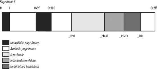
2.5.4. Process Page Tables
The linear address space of a process
is divided into two parts:
Linear addresses from 0x00000000 to 0xbfffffff can be addressed when the process runs in either User or Kernel Mode. Linear addresses from 0xc0000000 to 0xffffffff can be addressed only when the process runs in Kernel Mode.
When a process runs in User Mode, it issues linear addresses smaller than 0xc0000000; when it runs in Kernel Mode, it is executing kernel code and the linear addresses issued are greater than or equal to 0xc0000000. In some cases, however, the kernel must access the User Mode linear address space to retrieve or store data.
The PAGE_OFFSET macro yields the value 0xc0000000; this is the offset in the linear address space of a process where the kernel lives. In this book, we often refer directly to the number 0xc0000000 instead.
The content of the first entries of the Page Global Directory that map linear addresses lower than 0xc0000000 (the first 768 entries with PAE disabled, or the first 3 entries with PAE enabled) depends on the specific process. Conversely, the remaining entries should be the same for all processes and equal to the corresponding entries of the master kernel Page Global Directory
(see the following section).
2.5.5. Kernel Page Tables
The kernel maintains a set of page tables for its own use, rooted at a so-called master kernel Page Global Directory. After system initialization, this set of page tables is never directly used by any process or kernel thread; rather, the highest entries of the master kernel Page Global Directory are the reference model for the corresponding entries of the Page Global Directories of every regular process in the system.
We explain how the kernel ensures that changes to the master kernel Page Global Directory are propagated to the Page Global Directories that are actually used by processes in the section "Linear Addresses of Noncontiguous Memory Areas" in Chapter 8.
We now describe how the kernel initializes its own page tables. This is a two-phase activity. In fact, right after the kernel image is loaded into memory, the CPU is still running in real mode; thus, paging is not enabled.
In the first phase, the kernel creates a limited address space including the kernel's code and data segments, the initial Page Tables, and 128 KB for some dynamic data structures. This minimal address space is just large enough to install the kernel in RAM and to initialize its core data structures.
In the second phase, the kernel takes advantage of all of the existing RAM and sets up the page tables properly. Let us examine how this plan is executed.
2.5.5.1. Provisional kernel Page Tables
A provisional Page Global Directory
is initialized statically during kernel compilation, while the provisional Page Tables are initialized by the startup_32( ) assembly language function defined in arch/i386/kernel/head.S
. We won't bother mentioning the Page Upper Directories and Page Middle Directories anymore, because they are equated to Page Global Directory entries. PAE support is not enabled at this stage.
The provisional Page Global Directory is contained in the swapper_pg_dir variable. The provisional Page Tables are stored starting from pg0, right after the end of the kernel's uninitialized data segments (symbol _end in Figure 2-13). For the sake of simplicity, let's assume that the kernel's segments, the provisional Page Tables, and the 128 KB memory area fit in the first 8 MB of RAM. In order to map 8 MB of RAM, two Page Tables are required.
The objective of this first phase of paging is to allow these 8 MB of RAM to be easily addressed both in real mode and protected mode. Therefore, the kernel must create a mapping from both the linear addresses 0x00000000 through 0x007fffff and the linear addresses 0xc0000000 through 0xc07fffff into the physical addresses 0x00000000 through 0x007fffff. In other words, the kernel during its first phase of initialization can address the first 8 MB of RAM by either linear addresses identical to the physical ones or 8 MB worth of linear addresses, starting from 0xc0000000.
The Kernel creates the desired mapping by filling all the swapper_pg_dir entries with zeroes, except for entries 0, 1, 0x300 (decimal 768), and 0x301 (decimal 769); the latter two entries span all linear addresses between 0xc0000000 and 0xc07fffff. The 0, 1, 0x300, and 0x301 enTRies are initialized as follows:
The address field of entries 0 and 0x300 is set to the physical address of pg0, while the address field of entries 1 and 0x301 is set to the physical address of the page frame following pg0. The Present, Read/Write, and User/Supervisor flags are set in all four entries. The Accessed, Dirty, PCD, PWD, and Page Size flags are cleared in all four entries.
The startup_32( ) assembly language function also enables the paging unit. This is achieved by loading the physical address of swapper_pg_dir into the cr3
control register and by setting the PG flag of the cr0
control register, as shown in the following equivalent code fragment:
     movl $swapper_pg_dir-0xc0000000,%eax
     movl %eax,%cr3        /* set the page table pointer.. */
     movl %cr0,%eax
     orl $0x80000000,%eax
     movl %eax,%cr0        /* ..and set paging (PG) bit */
2.5.5.2. Final kernel Page Table when RAM size is less than 896 MB
The final mapping provided by the kernel page tables must transform linear addresses starting from 0xc0000000 into physical addresses starting from 0.
The _ _pa macro is used to convert a linear address starting from PAGE_OFFSET to the corresponding physical address, while the _ _va macro does the reverse.
The master kernel Page Global Directory
is still stored in swapper_pg_dir. It is initialized by the paging_init( ) function, which does the following:
Invokes pagetable_init( ) to set up the Page Table entries properly. Writes the physical address of swapper_pg_dir in the cr3 control register. If the CPU supports PAE
and if the kernel is compiled with PAE support, sets the PAE flag in the cr4 control register. Invokes _ _flush_tlb_all( ) to invalidate all TLB entries.
The actions performed by pagetable_init( ) depend on both the amount of RAM present and on the CPU model. Let's start with the simplest case. Our computer has less than 896 MB of RAM, 32-bit physical addresses are sufficient to address all the available RAM, and there is no need to activate the PAE mechanism. (See the earlier section "The Physical Address Extension (PAE) Paging Mechanism.")
The swapper_pg_dir Page Global Directory is reinitialized by a cycle equivalent to the following:
     pgd = swapper_pg_dir + pgd_index(PAGE_OFFSET); /* 768 */
     phys_addr = 0x00000000;
     while (phys_addr < (max_low_pfn * PAGE_SIZE)) {
         pmd = one_md_table_init(pgd); /* returns pgd itself */
         set_pmd(pmd, _ _pmd(phys_addr | pgprot_val(_ _pgprot(0x1e3))));
         /* 0x1e3 == Present, Accessed, Dirty, Read/Write,
                 Page Size, Global */
                 phys_addr += PTRS_PER_PTE * PAGE_SIZE; /* 0x400000 */
          ++pgd;
   }
We assume that the CPU is a recent 80 x 86 microprocessor supporting 4 MB pages and "global" TLB entries. Notice that the User/Supervisor flags in all Page Global Directory entries referencing linear addresses above 0xc0000000 are cleared, thus denying processes in User Mode access to the kernel address space. Notice also that the Page Size flag is set so that the kernel can address the RAM by making use of large pages (see the section "Extended Paging" earlier in this chapter).
The identity mapping of the first megabytes of physical memory (8 MB in our example) built by the startup_32( ) function is required to complete the initialization phase of the kernel. When this mapping is no longer necessary, the kernel clears the corresponding page table entries by invoking the zap_low_mappings( ) function.
Actually, this description does not state the whole truth. As we'll see in the later section "Fix-Mapped Linear Addresses," the kernel also adjusts the entries of Page Tables corresponding to the "fix-mapped linear addresses
."
2.5.5.3. Final kernel Page Table when RAM size is between 896 MB and 4096 MB
In this case, the RAM cannot be mapped entirely into the kernel linear address space. The best Linux can do during the initialization phase is to map a RAM window of size 896 MB into the kernel linear address space. If a program needs to address other parts of the existing RAM, some other linear address interval must be mapped to the required RAM. This implies changing the value of some page table entries. We'll discuss how this kind of dynamic remapping is done in Chapter 8.
To initialize the Page Global Directory, the kernel uses the same code as in the previous case.
2.5.5.4. Final kernel Page Table when RAM size is more than 4096 MB
Let's now consider kernel Page Table initialization for computers with more than 4 GB; more precisely, we deal with cases in which the following happens:
The CPU model supports Physical Address Extension (PAE
). The amount of RAM is larger than 4 GB. The kernel is compiled with PAE support.
Although PAE handles 36-bit physical addresses, linear addresses are still 32-bit addresses. As in the previous case, Linux maps a 896-MB RAM window into the kernel linear address space; the remaining RAM is left unmapped and handled by dynamic remapping, as described in Chapter 8. The main difference with the previous case is that a three-level
paging model is used, so the Page Global Directory is initialized by a cycle equivalent to the following:
     pgd_idx = pgd_index(PAGE_OFFSET); /* 3 */
     for (i=0; i<pgd_idx; i++)
         set_pgd(swapper_pg_dir + i, _ _pgd(_ _pa(empty_zero_page) + 0x001));
         /* 0x001 == Present */
     pgd = swapper_pg_dir + pgd_idx;
     phys_addr = 0x00000000;
     for (; i<PTRS_PER_PGD; ++i, ++pgd) {
         pmd = (pmd_t *) alloc_bootmem_low_pages(PAGE_SIZE);
         set_pgd(pgd, _ _pgd(_ _pa(pmd) | 0x001)); /* 0x001 == Present */
         if (phys_addr < max_low_pfn * PAGE_SIZE)
             for (j=0; j < PTRS_PER_PMD /* 512 */
                   && phys_addr < max_low_pfn*PAGE_SIZE; ++j) {
                 set_pmd(pmd, _ _pmd(phys_addr |
                                pgprot_val(_ _pgprot(0x1e3))));
                 /* 0x1e3 == Present, Accessed, Dirty, Read/Write,
                         Page Size, Global */
                 phys_addr += PTRS_PER_PTE * PAGE_SIZE; /* 0x200000 */
           }
     }
     swapper_pg_dir[0] = swapper_pg_dir[pgd_idx];
The kernel initializes the first three entries in the Page Global Directory corresponding to the user linear address space with the address of an empty page (empty_zero_page). The fourth entry is initialized with the address of a Page Middle Directory (pmd) allocated by invoking alloc_bootmem_low_pages( ). The first 448 entries in the Page Middle Directory (there are 512 entries, but the last 64 are reserved for noncontiguous memory allocation; see the section "Noncontiguous Memory Area Management" in Chapter 8) are filled with the physical address of the first 896 MB of RAM.
Notice that all CPU models that support PAE also support large 2-MB pages and global pages. As in the previous cases, whenever possible, Linux uses large pages to reduce the number of Page Tables.
The fourth Page Global Directory entry is then copied into the first entry, so as to mirror the mapping of the low physical memory in the first 896 MB of the linear address space. This mapping is required in order to complete the initialization of SMP
systems: when it is no longer necessary, the kernel clears the corresponding page table entries by invoking the zap_low_mappings( ) function, as in the previous cases.
2.5.6. Fix-Mapped Linear Addresses
We saw that the initial part of the fourth gigabyte of kernel linear addresses maps the physical memory of the system. However, at least 128 MB of linear addresses are always left available because the kernel uses them to implement noncontiguous memory allocation and fix-mapped linear addresses.
Noncontiguous memory allocation is just a special way to dynamically allocate and release pages of memory, and is described in the section "Linear Addresses of Noncontiguous Memory Areas" in Chapter 8. In this section, we focus on fix-mapped linear addresses.
Basically, a fix-mapped linear address is a constant linear address like 0xffffc000 whose corresponding physical address does not have to be the linear address minus 0xc000000, but rather a physical address set in an arbitrary way. Thus, each fix-mapped linear address maps one page frame of the physical memory. As we'll see in later chapters, the kernel uses fix-mapped linear addresses instead of pointer variables that never change their value.
Fix-mapped linear addresses are conceptually similar to the linear addresses that map the first 896 MB of RAM. However, a fix-mapped linear address can map any physical address, while the mapping established by the linear addresses in the initial portion of the fourth gigabyte is linear (linear address X maps physical address X-PAGE_OFFSET).
With respect to variable pointers, fix-mapped linear addresses are more efficient. In fact, dereferencing a variable pointer requires one memory access more than dereferencing an immediate constant address. Moreover, checking the value of a variable pointer before dereferencing it is a good programming practice; conversely, the check is never required for a constant linear address.
Each fix-mapped linear address is represented by a small integer index defined in the enum fixed_addresses data structure:
     enum fixed_addresses {
         FIX_HOLE,
         FIX_VSYSCALL,
         FIX_APIC_BASE,
         FIX_IO_APIC_BASE_0,
         [...]
         _ _end_of_fixed_addresses
     };
Fix-mapped linear addresses are placed at the end of the fourth gigabyte of linear addresses. The fix_to_virt( ) function computes the constant linear address starting from the index:
     inline unsigned long fix_to_virt(const unsigned int idx)
     {
     if (idx >= _ _end_of_fixed_addresses)
         _ _this_fixmap_does_not_exist( );
         return (0xfffff000UL - (idx << PAGE_SHIFT));
     }
Let's assume that some kernel function invokes fix_to_virt(FIX_IOAPIC_BASE_0). Because the function is declared as "inline," the C compiler does not generate a call to fix_to_virt( ), but inserts its code in the calling function. Moreover, the check on the index value is never performed at runtime. In fact, FIX_IOAPIC_BASE_0 is a constant equal to 3, so the compiler can cut away the if statement because its condition is false at compile time. Conversely, if the condition is true or the argument of fix_to_virt( ) is not a constant, the compiler issues an error during the linking phase because the symbol _ _this_fixmap_does_not_exist is not defined anywhere. Eventually, the compiler computes 0xfffff000-(3<<PAGE_SHIFT) and replaces the fix_to_virt( ) function call with the constant linear address 0xffffc000.
To associate a physical address with a fix-mapped linear address, the kernel uses the set_fixmap(idx,phys) and set_fixmap_nocache(idx,phys) macros. Both of them initialize the Page Table entry corresponding to the fix_to_virt(idx) linear address with the physical address phys; however, the second function also sets the PCD flag of the Page Table entry, thus disabling the hardware cache when accessing the data in the page frame (see the section "Hardware Cache" earlier in this chapter). Conversely, clear_fixmap(idx) removes the linking between a fix-mapped linear address idx and the physical address.
2.5.7. Handling the Hardware Cache and the TLB
The last topic of memory addressing deals with how the kernel makes an optimal use of the hardware caches. Hardware caches and Translation Lookaside Buffers play a crucial role in boosting the performance of modern computer architectures. Several techniques are used by kernel developers to reduce the number of cache and TLB misses.
2.5.7.1. Handling the hardware cache
As mentioned earlier in this chapter, hardware caches are addressed by cache lines. The L1_CACHE_BYTES macro yields the size of a cache line in bytes. On Intel models earlier than the Pentium 4, the macro yields the value 32; on a Pentium 4, it yields the value 128.
To optimize the cache hit rate, the kernel considers the architecture in making the following decisions.
The most frequently used fields of a data structure are placed at the low offset within the data structure, so they can be cached in the same line. When allocating a large set of data structures, the kernel tries to store each of them in memory in such a way that all cache lines are used uniformly.
Cache synchronization is performed automatically by the 80 x 86 microprocessors, thus the Linux kernel for this kind of processor does not perform any hardware cache flushing. The kernel does provide, however, cache flushing interfaces for processors that do not synchronize caches.
2.5.7.2. Handling the TLB
Processors cannot synchronize their own TLB cache automatically because it is the kernel, and not the hardware, that decides when a mapping between a linear and a physical address is no longer valid.
Linux 2.6 offers several TLB flush methods that should be applied appropriately, depending on the type of page table change (see Table 2-11).
Table 2-11. Architecture-independent TLB-invalidating methodsMethod name | Description | Typically used when |
|---|
flush_tlb_all | Flushes all TLB entries (including those that refer to global pages, that is, pages whose Global flag is set) | Changing the kernel page table entries | flush_tlb_kernel_range | Flushes all TLB entries in a given range of linear addresses (including those that refer to global pages) | Changing a range of kernel page table entries | flush_tlb | Flushes all TLB entries of the non-global pages owned by the current process | Performing a process switch | flush_tlb_mm | Flushes all TLB entries of the non-global pages owned by a given process | Forking a new process | flush_tlb_range | Flushes the TLB entries corresponding to a linear address interval of a given process | Releasing a linear address interval of a process | flush_tlb_pgtables | Flushes the TLB entries of a given contiguous subset of page tables of a given process | Releasing some page tables of a process | flush_tlb_page | Flushes the TLB of a single Page Table entry of a given process | Processing a Page Fault |
Despite the rich set of TLB methods offered by the generic Linux kernel, every microprocessor usually offers a far more restricted set of TLB-invalidating assembly language instructions. In this respect, one of the more flexible hardware platforms is Sun's UltraSPARC. In contrast, Intel microprocessors offers only two TLB-invalidating techniques:
All Pentium models automatically flush the TLB entries relative to non-global pages when a value is loaded into the cr3
register. In Pentium Pro and later models, the invlpg
assembly language instruction invalidates a single TLB entry mapping a given linear address.
Table 2-12 lists the Linux macros that exploit such hardware techniques; these macros are the basic ingredients to implement the architecture-independent methods listed in Table 2-11.
Table 2-12. TLB-invalidating macros for the Intel Pentium Pro and later processorsMacro name | Description | Used by |
|---|
_ _flush_tlb( ) | Rewrites cr3 register back into itself | flush_tlb, flush_tlb_mm,flush_tlb_range | _ _flush_tlb_global( ) | Disables global pages by clearing the PGE flag of cr4, rewrites cr3 register back into itself, and sets again the PGE flag | flush_tlb_all,flush_tlb_kernel_range | _ _flush_tlb_single(addr) | Executes invlpg assembly language instruction with parameter addr | flush_tlb_page |
Notice that the flush_tlb_pgtables method is missing from Table 2-12: in the 80 x 86 architecture nothing has to be done when a page table is unlinked from its parent table, thus the function implementing this method is empty.
The architecture-independent TLB-invalidating methods are extended quite simply to multiprocessor systems. The function running on a CPU sends an Interprocessor Interrupt (see "Interprocessor Interrupt Handling" in Chapter 4) to the other CPUs that forces them to execute the proper TLB-invalidating function.
As a general rule, any process switch implies changing the set of active page tables. Local TLB entries relative to the old page tables must be flushed; this is done automatically when the kernel writes the address of the new Page Global Directory into the cr3 control register. The kernel succeeds, however, in avoiding TLB flushes in the following cases:
When performing a process switch between two regular processes that use the same set of page tables (see the section "The schedule( ) Function" in Chapter 7). When performing a process switch between a regular process and a kernel thread. In fact, we'll see in the section "Memory Descriptor of Kernel Threads" in Chapter 9, that kernel threads
do not have their own set of page tables; rather, they use the set of page tables owned by the regular process that was scheduled last for execution on the CPU.
Besides process switches, there are other cases in which the kernel needs to flush some entries in a TLB. For instance, when the kernel assigns a page frame to a User Mode process and stores its physical address into a Page Table entry, it must flush any local TLB entry that refers to the corresponding linear address. On multiprocessor systems, the kernel also must flush the same TLB entry on the CPUs that are using the same set of page tables, if any.
To avoid useless TLB flushing in multiprocessor systems, the kernel uses a technique called lazy TLB mode
. The basic idea is the following: if several CPUs are using the same page tables and a TLB entry must be flushed on all of them, then TLB flushing may, in some cases, be delayed on CPUs running kernel threads.
In fact, each kernel thread does not have its own set of page tables; rather, it makes use of the set of page tables belonging to a regular process. However, there is no need to invalidate a TLB entry that refers to a User Mode linear address, because no kernel thread accesses the User Mode address space.
When some CPUs start running a kernel thread, the kernel sets it into lazy TLB mode. When requests are issued to clear some TLB entries, each CPU in lazy TLB mode does not flush the corresponding entries; however, the CPU remembers that its current process is running on a set of page tables whose TLB entries for the User Mode addresses are invalid. As soon as the CPU in lazy TLB mode switches to a regular process with a different set of page tables, the hardware automatically flushes the TLB entries, and the kernel sets the CPU back in non-lazy TLB mode. However, if a CPU in lazy TLB mode switches to a regular process that owns the same set of page tables used by the previously running kernel thread, then any deferred TLB invalidation must be effectively applied by the kernel. This "lazy" invalidation is effectively achieved by flushing all non-global TLB entries of the CPU.
Some extra data structures are needed to implement the lazy TLB mode. The cpu_tlbstate variable is a static array of NR_CPUS structures (the default value for this macro is 32; it denotes the maximum number of CPUs in the system) consisting of an active_mm field pointing to the memory descriptor of the current process (see Chapter 9) and a state flag that can assume only two values: TLBSTATE_OK (non-lazy TLB mode) or TLBSTATE_LAZY (lazy TLB mode). Furthermore, each memory descriptor includes a cpu_vm_mask field that stores the indices of the CPUs that should receive Interprocessor Interrupts related to TLB flushing. This field is meaningful only when the memory descriptor belongs to a process currently in execution.
When a CPU starts executing a kernel thread, the kernel sets the state field of its cpu_tlbstate element to TLBSTATE_LAZY; moreover, the cpu_vm_mask field of the active memory descriptor stores the indices of all CPUs in the system, including the one that is entering in lazy TLB mode. When another CPU wants to invalidate the TLB entries of all CPUs relative to a given set of page tables, it delivers an Interprocessor Interrupt to all CPUs whose indices are included in the cpu_vm_mask field of the corresponding memory descriptor.
When a CPU receives an Interprocessor Interrupt related to TLB flushing and verifies that it affects the set of page tables of its current process, it checks whether the state field of its cpu_tlbstate element is equal to TLBSTATE_LAZY. In this case, the kernel refuses to invalidate the TLB entries and removes the CPU index from the cpu_vm_mask field of the memory descriptor. This has two consequences:
As long as the CPU remains in lazy TLB mode, it will not receive other Interprocessor Interrupts related to TLB flushing. If the CPU switches to another process that is using the same set of page tables as the kernel thread that is being replaced, the kernel invokes _ _flush_tlb( ) to invalidate all non-global TLB entries of the CPU.
|
|
|
|
|

 LINUX
LINUX 
 ]
]